background image

21 


6. Troubleshooting 

Review the troubleshooting procedures in this section if a problem develops with your machine. If you 
need replacement parts or additional help with a procedure, callb us.   
Note: Please gather the serial number and manufacture date of your machine before calling. 


Symptom 

Possible Cause 

Possible Solution 

Machine does not 

start, or powersupply 

fuse/breaker trips 

immediately after 

startup. 

1. Dust collector not properly connected to 

ducting. 

2. Incorrect power supply voltage or circuit 

size. 

3. Power supply circuit breaker tripped or 

fuse blown. 

4. Motor overheated. 

5. Machine circuit breaker has tripped. 

6. Wiring open/has high resistance. 

7. Power switch/circuit breaker at fault. 

8. Start capacitor at fault. 

9. Motor at fault. 

1. Connect dust collector to ducting. 

2. Ensure correct power supply voltage and circuit 

size. 

3. Ensure circuit is sized correctly and free of shorts.

Reset circuit breaker or replace fuse. 

4. Allow motor to cool, reset overload if necessary. 

5. Reset circuit breaker on switch. 

6. Check/fix broken, disconnected, or corroded 

wires. 

7. Test/replace. 

8. Replace. 

9. Test/repair/replace. 

Machine seems 

underpowered. 

1. Motor overheated. 

2. Dust-collection ducting problem. 

3. Canister filter clogged/at fault. 

4. Dust collector too far from machine or 

undersized for dust-collection system. 

5. Run capacitor at fault. 

6. Motor bearings at fault. 

1. Allow motor to cool, reset overload if necessary. 

2. Clear blockages, seal leaks, use smooth-wall 

duct, eliminate bends, close other branches. 

3. Clean canister filter; replace canister filter. 

4. Move closer to machine/redesign ducting layout/ 

upgrade dust collector. 

5. Test/repair/replace. 

6. Test by rotating shaft; rotational grinding/loose 

shaft requires bearing replacement. 

Machine has vibration 

or noisy operation. 

1. Motor or component loose. 

2. Motor fan rubbing on fan cover. 

3. Motor mount loose/broken. 

4. Impeller damaged, unbalanced, or loose.

5. Motor bearings at fault. 

6. Motor shaft bent. 

1. Inspect/replace damaged bolts/nuts, and 

retighten with thread-locking fluid. 

2. Fix /replace fan cover; replace loose/damaged 

fan. 

3. Tighten/replace. 

4. Inspect/tighten/replace. 

5. Test by rotating shaft; rotational grinding/loose 

shaft requires bearing replacement. 

6. Test with dial indicator. Replace motor if 

damaged. 

Loud, repetitious 

noise, or excessive 

vibration coming from 

dust collector (non-

motor related). 

1. Dust collector not on a flat surface and 

wobbles. 

2. Impeller damaged and unbalanced. 

3. Impeller loose on the motor shaft. 

1. Stabilize dust collector; lock casters. 

2. Inspect/replace. 

3. Secure impeller; replace motor and impeller as a 

set if motor shaft and impeller hub are damaged. 


Содержание 107571

Страница 1: ...AW145CE Cyclone Extractor Code 107571 Original Instructions AT 09 02 2022 BOOK VERSION 01 ...

Страница 2: ...en issued by Laizhou Planet Machinery Co Ltd at Yutai West Street Laizhou 261400 Shandong China Mainland and complies with the relevant essential health and safety requirements 2006 42 EC EN 62233 2008 EN 60335 2 69 2012 EN 60335 1 2012 A11 A13 A1 A14 A2 declares that the machinery described This machine complies with the following directives EU Declaration of Conformity Signed Andrew Parkhouse Op...

Страница 3: ...ctor 8 3 4 2 To assemble machine 9 3 5 Initial commissioning 14 3 6 Accessories for dust collector 15 4 Operation 16 4 1 Remote control and electrical control box 17 4 1 1 Remote control 17 4 1 2 Control box 17 4 2 Tips for optimum performance 18 4 3 Required CFMs 18 5 Maintenance 19 5 1 Schedule 19 5 2 Cleaning canister filter 19 5 3 Removing Replacing collection drum bag 19 5 4 Removing Replacin...

Страница 4: ... notice The illustrations of the machine may be different from the illustrations in these instructions with regard to a few details However this does not have any influence on the operability of the machine Therefore no claims may be derived from the indications and descriptions Your suggestion with regard to these operating instructions are an important contribution to optimising our work which w...

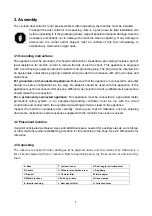
Страница 5: ...ossible hazardous conditions This manual uses a series of symbols and signal words intended to convey the level of importance of the safety messages The progression of symbols is described below Remember that safety messages by themselves do not eliminate danger and are not a substitute for proper accident prevention measures WARNING Some dust created by power sanding sawing grinding drilling and ...

Страница 6: ...hands and clothing away from moving parts Always tie back or cover long hair Wear non slip footwear to avoid accidental slips which could cause a loss of workpiece control 1 11 Personal protective equipment Dirty or contaminated personal protective equipment can cause illness Clean your personal protective equipment after each use and once a week 1 2Safety instructions for dust collector Long term...

Страница 7: ...the machine unattended or doing any service cleaning maintenance or adjustments SUSPENDED DUST PARTICLES AND IGNITION SOURCES Do not operate the dust collector in areas where explosion risks are high Areas of high risk include but are not limited to areas near pilot lights open flames or other ignition sources FIRE SUPPRESSION Only operate the dust collector in locations that contain a fire suppre...

Страница 8: ...op environment is different Accidents are frequently caused by lack of familiarity or failure to pay attention Use this machine with respect and caution to lessen the possibility of operator injury If normal safety precautions are overlooked or ignored serious personal injury may occur FAILURE TO FOLLOW THESE RULES MAY RESULT IN SERIOUS PERSONAL INJURY FOR YOUR OWN SAFETY READ AND UNDERSTAND THE I...

Страница 9: ...eed 50Hz RPM 2850r min Motor speed 60Hz RPM 3450r min Impeller size MM Φ330mm Inlet hole size MM Φ150mm Number of Intake holes MM 3XΦ100mm Bag size MM Φ500x1100mm Bag volume m 0 216 m Air speed 50Hz m h 1450 m h Air speed 60Hz m h 1500 m h Filter area m 2 6 m Filter capacity Micro 1 Noise level dB 84 dB Width X Depth X Height MM 1200X660X1750 Packing size MM 1020 590 900mm 1240 412 170mm 650 430 4...

Страница 10: ...s appliance If the appliance must be reconnected for use on a different type of electric circuit qualified service personnel should make the reconnection For a permanently connected appliance This appliance must be connected to a grounded metal permanent wiring system or an equipment grounding conductor must be run with the circuit conductors and connected to the equipment grounding terminal or le...

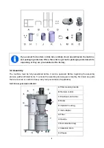
Страница 11: ...st preventative if applicable 3 4 1 Know your dust collector If you cannot find an item on this list carefully check around inside the machine and packaging materials Often these items get lost in packaging materials while unpacking or they are pre installed at the factory A Filter cleaning handle B Remote control C Electrical control box D Motor E Impleller housing F Inlet adapter G Filter H Hand...

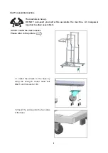
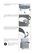
Страница 12: ...le assemble the machine 2 3 manpower required to safely assemble it STEP 1 Install the main bracket Please refer to the picture 1 1 Install the wheels to the base by using the hexagon socket head bolt M6x15 and flat washer Φ6 1 2 Insert the end cap into the four sides of the base ...

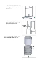
Страница 13: ...ase by using the hexagon socket head bolt M6x15 and washer Φ6 1 4 Install the handle to the bracket by using hexagon socket head cap bolt M8X40 washer Φ8 and nut M8 STEP 2 Install the dust collection drum Please refer to the picture ...

Страница 14: ...4X12 flat washer Φ4 and nut M4 2 3 Install the handle bar to the dust collection drum by hexagon socket head bolt M8X20 and flat washer 8 self locking nut M8 2 4 Place the inner drum into the dust collect bag and then put them togher into the collection drum NOTE The positons of two windows inner outer should align to each other ...

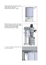
Страница 15: ...r filter by bag clamp Please refer to the picture STEP 4 Final step Combine the impller housing machine bracket cyclone funnel assembly canister filter together Please refer to the picture 4 1 Fasten the impeller housing on the main bracket by bolt M8X20 ...

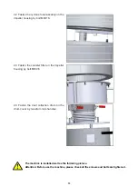
Страница 16: ... machine please check all the screws and bolts are tightened 4 2 Fasten the cyclone funel assemly on the impeller housing by bolt M8X16 4 3 Fasten the canister filter on the impeller housing by bolt M8X16 4 3 Fasten the dust collection drum on the drum cover by two drum lock handles ...

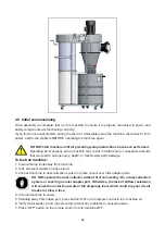
Страница 17: ...chine property damage To test run machine 1 Clear all setup tools away from machine 2 Lock all swivel casters on base stand 3 Connect machine to dust collection system or place covers over inlet adapter ports DO NOT operate the dust collector without first connecting it to a dust collection system or covering an inlet adapter port Otherwise the lack of airflow resistance will cause the motor to op...

Страница 18: ... Optional accessories for dust collector 4 Blast gate Elbow Adaptor Connector Connector Canister filter Flexible hose Hose clamp Bag clamp Dust bag More accessories available please inquire the local retailer ...

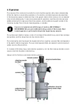
Страница 19: ...ienced with this type of machine WE STRONGLY RECOMMEND that you seek additional training outside of this manual Read books magazines or get formal training before beginning any projects This cyclone dust collector creates a vortex of incoming air that extracts heavy wood chips and large dust particles and then drops them into the collection drum The remaining fine dust travels past the impeller an...

Страница 20: ...timing the machine to run at 2 hours 4 hours 6 hours and 8 horus The bottom buttons is ON to start the machine Note The remote control requires one 23A 12V battery for operation 4 1 2 Control box Except controlling the machine by remote control the three buttons on the control box could be also used when need Green for ON start the machine Yellow for TIMER timing the running time Red for OFF Turno...

Страница 21: ...mpler the system the more efficient and less costly it will be 4 3Required CFMs Since each machine produces a different amount of sawdust the requirements for the minimum amount of CFM to move that sawdust is unique to the machine for example a planer produces more sawdust than a table saw Knowing this required CFM is important to gauging which size of duct to use Refer to the figure below for a c...

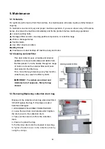
Страница 22: ...ddles to remove dust buildup and debris from the filter pleats Turn the handle through its range of motion to clean the canister filter and knock dust cake into the filter bag For a more thorough cleaning every few months under heavy use wash the filter by hand IMPORTANT To contain wood dust and minimize risk of exposure firmly tie bag closed 5 3 Removing Replacing collection drum bag Dispose of t...

Страница 23: ...cleaning or washing it does not improve dust collection performance the canister filter must be replaced To remove and replace canister filter 1 DISCONNECT MACHINE FROM POWER 2 Loose the hexagon socket button screw M6X15 which fixed the seal pad and canister filter to the main housing assembly 3 Install the seal pad and new canister filter to the main housing assembly by the screw M6X15 Dust expos...

Страница 24: ...ogged at fault 4 Dust collector too far from machine or undersized for dust collection system 5 Run capacitor at fault 6 Motor bearings at fault 1 Allow motor to cool reset overload if necessary 2 Clear blockages seal leaks use smooth wall duct eliminate bends close other branches 3 Clean canister filter replace canister filter 4 Move closer to machine redesign ducting layout upgrade dust collecto...

Страница 25: ...Remove ducting from dust collector inlet and unblock restriction A plumbing snake may be necessary 4 Relocate dust collector closer to point of suction re secure ducts remove sharp bends 5 Only process lumber with less than 20 moisture content 6 Seal eliminate all ducting leaks close dust ports for lines not being used Refer to Designing the System in manual 7 Open 1 or 2 more blast gates to diffe...

Страница 26: ...7 Diagram and part list 7 1 Diagram 23 ...

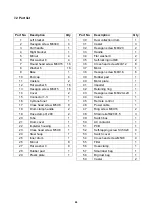
Страница 27: ...6 41 Impeller 1 13 Hexagon screw M6X15 16 42 Retaining ring 1 14 Cover 2 43 Hexagon screw M6X20 Left 1 15 Connector 1 3 1 44 Volute 1 16 Cyclone funel 1 45 Remote control 1 17 Cross head screw M5X8 8 46 Power cable 1 18 Drum clamp handle 2 47 Ring screw M8X16 2 19 Hose clamp Ф 200 2 48 Strain relief M20X1 5 3 20 Tube 1 49 Switch box 1 21 Drum cover 1 50 AC contactor 1 22 Impleller housing 1 51 PCB...

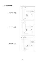
Страница 28: ...25 7 3 Wiring diagram 120V 60HZ 230V 50HZ 400V 50HZ ...

Страница 29: ......

Страница 30: ...ears For more information visit axminstertools com 3years Axminster Tools Axminster Devon EX13 5PH axminstertools com The packaging is suitable for recycling Please dispose of it in a responsible manner Do not dispose of electric tools together with household waste material By law they must be collected and recycled separately EU Countries Only ...

Отзывы: