AXIOMTEK GOT610-837 Скачать руководство пользователя страница 28

GOT610-837 

User’s Manual


22 


AMI BIOS Setup Utility


3.2 

Menu Bar


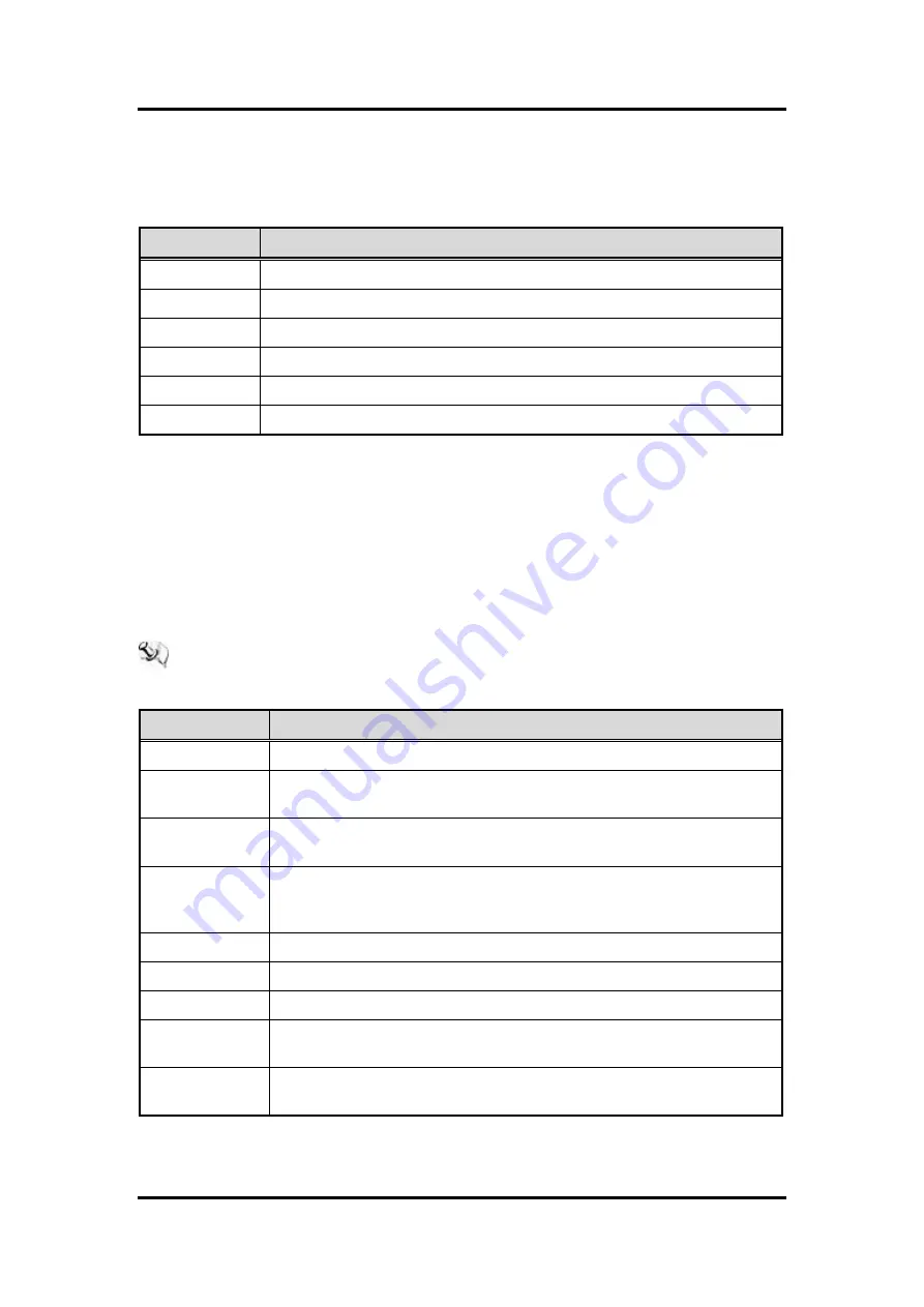
The top of the screen has a menu bar with the following selections: 
 

Menu Bar 

Description 

Main


To set up the system time/date information. 

Advanced 

To set up the advanced BIOS features. 

Chipset 

To display the North & South bridge (USB configuration) status. 

Security


To set up the security features. 

Boot


To set up the default system device to locate and load the operating system. 

Exit 

To exit the current screen or the BIOS setup utility. 

 
Use <

> key or <

> key to choose among the selections on the menu bar, and then press 

<Enter> to get into the sub screen. You can also use the mouse to click your required item. 
 

3.3 

Navigation Keys


The BIOS setup/utility uses a key-based navigation system called hot keys. Most of the BIOS 
setup utility hot keys can be used at any time during the setup navigation process. These keys 
include <F1>, <F7>, <Enter>, <ESC>, <Arrow> keys, and so on. 
 

  NOTE  Some of the navigation keys may differ from one screen to another.


Please check the following table for the function description of each navigation key. 

Hot Keys 

Description 



 Left/Right


The Left and Right <Arrow> keys allow you to select a setup screen. 



 Up/Down


The  Up  and  Down  <Arrow>  keys  allow  you  to  select  a  setup  screen  or 
sub-screen. 

+

 Plus/Minus


The  Plus  and  Minus  <Arrow>  keys  allow  you  to  change  the  field  value  of  a 
particular setup item. 

Enter 

The  <Enter>  key  allows  you  to  display  or  change  the  setup  option  listed  for  a 
particular  setup  item.  The  <Enter> key  can also  allow  you to  display  the  setup 
sub- screens. 

F1


The <F1> key allows you to display the General Help screen. 

F7 

Discard changes. 

F9


The <F9> key allows you to load optimal default values for all the settings. 

F10


The <F10> key allows you to save any changes you have made and exit Setup. 
Press the <F10> key to save your changes. 

Esc   

The <Esc> key allows you to discard any changes you have made and exit the 
Setup. Press the <Esc> key to exit the setup without saving your changes. 


Содержание GOT610-837

Страница 1: ...GOT610 837 10 4 XGA TFT For Heavy Duty Vehicle Touch Panel Computer User s Manual...

Страница 2: ...tion in this manual Axiomtek reserves the right to change or revise this document and or product at any time without notice No part of this document may be reproduced stored in a retrieval system or t...

Страница 3: ...ained technician is allowed to do so Integrated circuits on computer boards are sensitive to static electricity To avoid damaging chips from electrostatic discharge observe the following precautions B...

Страница 4: ...us 9 2 4 COM 1 Serial Port Connector 10 2 5 USB 2 0 10 2 6 LAN 11 2 7 DIO 12 2 7 1 Digital I O Specification 12 2 7 2 Digital I O Software Programming 13 2 7 3 Digital Input Wiring 14 2 7 4 Digital Ou...

Страница 5: ...nced Menu 24 3 6 Chipset Menu 31 3 7 Security Menu 33 3 8 Boot Menu 34 3 9 Exit Menu 35 Chapter 4 Drivers and Installation 37 4 1 System 37 4 2 Touch Screen 37 4 3 Configuration Center Software 40 4 3...

Страница 6: ...vi This page is intentionally left blank...

Страница 7: ...ndly user interface make it a professional yet easy to use panel computer The GOT610 837 is ideal for vehicle mounted terminal applications in heavy duty vehicles especially suited for forklift and fl...

Страница 8: ...a Megatrends UEFI BIOS 1 2 2 I O System Standard I O 1 x RS 232 422 485 with isolated 1 5KV default RS 232 4 x USB 2 0 three in I O line one in top side 1 x DIO with isolated 1 5KV D Sub connector 6 i...

Страница 9: ...ation temperature 30 C to 55 C Relative humidity 10 to 95 40 C Non Condensing Power input 9 60VDC Vibration Refer to IEC60721 3 5 Class 5M3 10 to 500 Hz 3 38G random for 2 5 SSD NOTE 1 All specificati...

Страница 10: ...GOT610 837 User s Manual 4 Introduction 1 3 Dimensions The following diagrams show the dimensions and outlines of the GOT610 837...

Страница 11: ...n for I O locations of the GOT610 837 Definitions of the front hot keys Definitions of the rear I O functions No Function No Function 1 DC in 6 3 x USB 2 0 type A 2 AX ATX mode switch 7 DIO 6 in 2 out...

Страница 12: ...G LTE SIM slot 13 USB 2 0 A type 1 5 Packing List A complete bundled package of the GOT610 837 should contain the following items GOT610 837 unit x 1 Driver CD x1 Phoenix connector x 2 Power 4Pin 1 DI...

Страница 13: ...flexible expansions for you to meet different demands The chapter explains how to install the hardware parts including Open cover I O cover and back cover Vin 9 60VDC Serial ports USB ports Ethernet...

Страница 14: ...Open cover This section tells users how to open back covers Please follow the steps below Open I O Cover Unscrew eight screws on the I O cover Please refer the photo below Open back cover Unscrew six...

Страница 15: ...ssignment table below Pin Description Definition 1 V For DC power in V 2 ACC For ACC Ignition 3 V For DC power in V 4 G Chassis GND 2 3 CANBus This system supports one CANBus with isolated 1 5KV The p...

Страница 16: ...rom the BIOS items Pin RS 232 RS 422 RS 485 1 DCD Data carrier detect TX Data 2 RXD Receive data TX Data 3 TXD Transmit data RX NC 4 DTR Data terminal ready RX NC 5 GND ground NC NC 6 DSR Data set rea...

Страница 17: ...em is equipped with an RJ 45 connector for Gigabit LAN To connect the board to a 10 100 1000 Base T hub just plug one end of the cable into LAN and connect the other end to a 10 100 1000 Base T hub Pi...

Страница 18: ...e 0 to 30VDC at 25Hz Input level for dry contacts Logic level 0 close to ground Logic level 1 open Input level for wet contacts Logic level 1 3VDC max Logic level 0 10VDC min to 30VDC max source to di...

Страница 19: ...are and Installation 13 2 7 2 Digital I O Software Programming I2C to GPIO PCA9554PW GPIO Group0 3 0 is Output Group0 7 4 is Input I2C address 0b0100100x Registers Register 0 Input Group0 register Reg...

Страница 20: ...837 User s Manual 14 Hardware and Installation 2 7 3 Digital Input Wiring DRY contact Logic level 0 close to ground Logic level 1 open WET contact Logic level 1 3VDC max Logic level 0 10VDC min to 30V...

Страница 21: ...GOT610 837 User s Manual Hardware and Installation 15 2 7 4 Digital Output Wiring...

Страница 22: ...iFi 3G module Please choose slot 1 when installing a WiFi 3G module and refer to the following instructions and illustrations to install the module Step 1 Open the back cover and locate the Mini Card...

Страница 23: ...to install mSATA Please choose slot 2 when installing an mSATA card and refer to the following instructions and illustration In addition please set up the BIOS IDE Configuration to mSATA Step 1 Open...

Страница 24: ...settings below for your requirements Jumper settings on the main board Jumper Default Setting Jumper Setting JP5 Normal Clear CMOS Short 1 2 Short 2 3 Jumper settings on the I O board Jumper Default S...

Страница 25: ...light dimming control please access the programming library manual included in the user s DVD used to call the API DLL 1 GOT710_API dll AXIOMTEK API DLL file 2 GOT710_API_V1_2 pdf AXIOMTEK API program...

Страница 26: ...LED indications of the device 2 12 Auto dimming Because the human eye perceiving brightness is nonlinear PWM duty must be set percentage at each stage of opening and closing LCD Backlight Level 10 100...

Страница 27: ...inue with its test routines 2 After you press the Del key the main BIOS setup menu displays You can access the other setup screens from the main BIOS setup menu such as the Advanced and Chipset menus...

Страница 28: ...de F1 F7 Enter ESC Arrow keys and so on NOTE Some of the navigation keys may differ from one screen to another Please check the following table for the function description of each navigation key Hot...

Страница 29: ...e set up as described below The Main BIOS setup screen is shown below BIOS Information Display the auto detected BIOS information System Date Time Use this option to change the system time and date Hi...

Страница 30: ...n select any of the items on the left frame of the screen to go to the sub menus NCT6106D Super IO Configuration NCT6106D H W Monitor CPU Configuration IDE Configuration Miscellaneous Configuration CS...

Страница 31: ...GOT610 837 User s Manual AMI BIOS Setup Utility 25 NCT6106D Super IO Configuration Use this screen to select options for the Super IO Configuration and change the value of the selected option...

Страница 32: ...GOT610 837 User s Manual 26 AMI BIOS Setup Utility NCT6106D H W Monitor This screen shows the hardware health configurations...

Страница 33: ...GOT610 837 User s Manual AMI BIOS Setup Utility 27 CPU Configuration This screen shows the CPU Configuration and Intel virtualization technology enable disable selected...

Страница 34: ...IDE Configuration You can use this screen to select options for SATA configurations and change the value of the selected option SATA Mode Use this item to choose the SATA operation mode Here are the...

Страница 35: ...GOT610 837 User s Manual AMI BIOS Setup Utility 29 Miscellaneous Configuration Use this screen to select options for different OS Windows 8 X Android and Windows 7...

Страница 36: ...GOT610 837 User s Manual 30 AMI BIOS Setup Utility CSM Configuration Enable is Legacy mode Disable is UEFI mode USB Configuration Display USB device configurations...

Страница 37: ...The Chipset menu will display the available devices on your system for you to configure the boot settings and the boot priority North Bridge This screen shows the North Bridge memory information You c...

Страница 38: ...GOT610 837 User s Manual 32 AMI BIOS Setup Utility South Bridge USB Configuration Only supports USB2 0 EHCI...

Страница 39: ...GOT610 837 User s Manual AMI BIOS Setup Utility 33 3 7 Security Menu In this section you may set change or clear the supervisor user password for the system...

Страница 40: ...of seconds to wait for the setup activation key Bootup NumLock State Use this item to select the power on state for the NumLock The default setting is on Quiet Boot Use this item to enable or disable...

Страница 41: ...GOT610 837 User s Manual AMI BIOS Setup Utility 35 3 9 Exit Menu NOTE Load default before updating g TXE firmware and restart...

Страница 42: ...GOT610 837 User s Manual 36 AMI BIOS Setup Utility This page is intentionally left blank...

Страница 43: ...fore installation Step 1 Insert the driver CD and select Drivers Step 2 Select all files and follow the installing procedure 4 2 Touch Screen The GOT610 837 adopts a 5 wire analog resistive touch scre...

Страница 44: ...ndows OS To facilitate installation of the touch screen driver you should read the instructions in this chapter carefully before you start installation Step 1 Insert the driver CD and follow the path...

Страница 45: ...ion 39 Step 4 Select the Standard Calibrate tab Step 5 Calibrations To adjust the display of the touch panel click Calibration and follow the calibrating point to do calibration there are five points...

Страница 46: ...will guide you to install the Configuration Center Software Just follow the follow the on screen instructions step by step Before you start please be reminded to run the installer as administrator 4 3...

Страница 47: ...s Manual Drivers and Installation 41 Step 2 Confirm installation and click Next to continue installing Step 3 Please wait when you see the following screen Step 4 When installation is completed click...

Страница 48: ...installation completed please reboot your system to activate the software 4 3 2 Configuration Center Homepage You can double check the icon in notification area to show homepage System Information Thi...

Страница 49: ...Function Enable Disable custom action when the engine is turned off Ignition Off Action What action do you want to execute when the engine is turned off Timeout Seconds If the action does not execute...

Страница 50: ...GOT610 837 User s Manual Drivers and Installation 44 Watchdog Timer Watchdog timer Time out value 10 225 Mode Watchdog timer count mode second minute...

Страница 51: ...tallation 45 Volume Brightness Volume and Brightness Set the system volume and brightness Automatic Brightness Dimming Enable Disable auto dim feature If you enable this feature you will not be able t...

Страница 52: ...key Default action Execute Program Select the program you want to execute when front key click Custom Key 1 Click Detect button to start to record keys you want to simulate when front key click 2 Clic...

Страница 53: ...ery custom action When battery is lower than The lower limit value of battery capacity percent Action What action do you want to execute when battery is lower than lower limit Timeout If the action do...

Страница 54: ...GOT610 837 User s Manual Drivers and Installation 48 This page is intentionally left blank...

Отзывы: