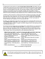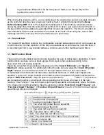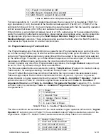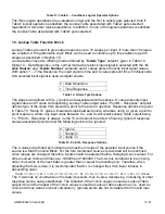
UMAX030440 Version 2B 11-51
log will still use different OC for the two types of faults, even though they will be
reported the same in the DTC.
When the fault is linked to a DTC, a non-volatile log of the occurrence count (OC) is kept. As soon
as the controller detects a new (previously inactive) fault, it will start decrementing the
Delay
Before Sending DM1
timer for the Diagnostic function block. If the fault has remained present
during the delay time, then the controller will set the DTC to active, and it will increment the OC in
the log. A DM1 will immediately be generated that includes the new DTC. The timer is provided so
that intermittent faults do not overwhelm the network as the fault comes and goes, since a DM1
message would be sent every time the fault shows up or goes away.
1.6. Constant Data
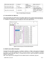
The Constant Data Block contains four configurable constant data setpoints which can be used as
a control source for other functions. While they are available as a control source to all functions, it
is recommended not to use constant data as a control source for the Set-Reset Latch Block.
1.7. Math Function Block
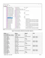
There are four mathematical function blocks that allow the user to define basic algorithms. A math
function block can take up to six input signals. Each input is then scaled according to the
associated limit and scaling setpoints.
Inputs are converted into percentage value based on t
he “
Input X Minimum
” and “
Input X
Maximum
” values selected. For additional control the user can also adjust the “
Input X Decimal
Digits
” setpoint to increase the resolution of the input data and the min and max values.
A mathematical function block includes three selectable functions, in which each implements
equation
A operator B
, where A and B are function inputs and operator is function selected with a
setpoint “
Math Function X
”. Setpoint options are presented in
Table 11. The functions
are connected together, so that result of the preceding function goes into Input A of the next
function. Thus Function 1 has both Input A and Input B selectable with setpoints, where Functions
2 to 4 have only Input B selectable. Input is selected by setting “
Function X Input Y Source
” and
“
Function X Input Y Number
”. If “
Function X Input B Source
” is set to 0 ‘
Control not used’
signal
goes through function unchanged.
𝑀𝑎𝑡ℎ 𝐵𝑙𝑜𝑐𝑘 𝑂𝑢𝑡𝑝𝑢𝑡 = (((𝐴1 𝑜𝑝1 𝐵1)𝑜𝑝2 𝐵2)𝑜𝑝3 𝐵3 ) 𝑜𝑝4 𝐵4
0
=, True when InA equals InB
1
!=, True when InA not equal InB
2
>, True when InA greater than InB
3
>=, True when InA greater than or equal InB
4
<, True when InA less than InB
5
<=, True when InA less than or equal InB
6
OR, True when InA or InB is True
7
AND, True when InA and InB are True
8
XOR, True when either InA or InB is True, but not both
9
+, Result = InA plus InB
10
-, Result = InA minus InB
11
x, Result = InA times InB


