Avigilon CBS350-24FP-4G Series Скачать руководство пользователя страница 5

Configuring 8- and 24-Port Managed PoE
Switches

The managed PoE switch can be managed over your IP network using the web-based interface, or by using
the command-line interface through the console port. Using the console port requires advanced user skills
and is only supported on certain models. In this guide we will only cover the web-based interface
configuration.

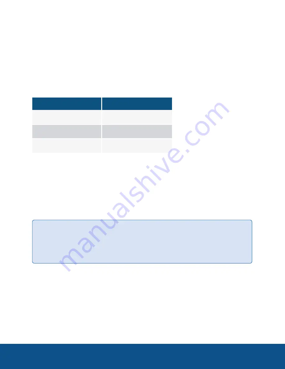
The following table shows the default settings used when configuring your switch for the first time.

Parameter

Default Value

Username

cisco

Password

cisco

IP address

192.165.0.254/24

Configuring Your Switch Using the Web-based Interface

To access the managed PoE switch using the web-based interface, you must know the IP address that the
managed PoE switch is using. The managed PoE switch uses the factory default IP address of 192.168.1.254,
with a subnet of /24. When the managed PoE switch is using the factory default IP address, the System LED
flashes continuously. When the managed PoE switch is using a DHCP server-assigned IP address or an
administrator has configured a static IP address, the System LED is a steady green (DHCP is enabled by
default).

Tip:

Access to the managed PoE switch will be lost if its IP address is changed, either by a DHCP

server or manually while tou are configuring the managed PoE switch through its web-based
interface. . You must enter the new IP address that the managed PoE switch is using into your
browser to reconnect to the web-based interface.

Accessing the Managed PoE Switch Web-based Interface

To access the web-based management interface on the managed PoE switch, you need to connect a
computer to any PoE port on the switch, and configure the Network Interface Connection (NIC) on the
computer to communicate with the switch on the local private network.

Configuring 8- and 24-Port Managed PoE Switches

2

Содержание CBS350-24FP-4G Series

Страница 1: ...User Guide 8 and 24 Port Managed PoE Switches CBS350 8FP E 2G and CBS350 24FP 4G xx...

Страница 2: ...r other intellectual property rights of Avigilon Corporation or its licensors This document has been compiled and published using product descriptions and specifications available at the time of publi...

Страница 3: ...2 Accessing the Managed PoE Switch Web based Interface 2 Basic or Advanced Display Mode 5 Configuration Wizards 6 Getting Started Wizard 6 VLAN Configuration Wizard 7 ACL Configuration Wizard 8 Enhan...

Страница 4: ...es that these PoE switches are connected with no change to their default settings Provide this guide to the owner of the equipment for future use This guide provides configuration information for depl...

Страница 5: ...254 with a subnet of 24 When the managed PoE switch is using the factory default IP address the System LED flashes continuously When the managed PoE switch is using a DHCP server assigned IP address...

Страница 6: ...stem Control Panel Network and Internet Network and Sharing Center 2 Click Change adapter settings from the left navigation menu The Network Connections window is displayed 3 Double click on the icon...

Страница 7: ...0 7 Open a web browser window type the switch IP address in the address bar and press Enter For example http 192 168 1 254 8 When the login page appears choose the language that you prefer to use in t...

Страница 8: ...the web based interface by clicking on the Save icon Exiting before you save your configuration results in all changes being lost Basic or Advanced Display Mode The managed PoE switch web based GUI i...

Страница 9: ...of the device MAC address in hex format n User Defined Enter the hostname Use only letters digits and hyphens Host names cannot begin or end with a hyphen No other symbols punctuation characters or bl...

Страница 10: ...network traffic and isolate broadcast domains Segmentation of a network helps to increase security reliability and efficiency of a network In the context of the Avigilon Control Center end to end solu...

Страница 11: ...LAN by clicking with mouse on the required ports in the graphical display 9 Click Next to see the summary of the information that you entered 10 Click Apply ACL Configuration Wizard An access control...

Страница 12: ...mask if relevant Source MAC Wildcard Mask Select Any if all destination addresses are acceptable or User defined to enter a destination Destination MAC Address Select Any if all destination addresses...

Страница 13: ...a port from the drop down list Source IP Address Select Any if all source addresses are acceptable or User defined to enter a source address or range of source addresses Source IP Value Enter the IP...

Страница 14: ...d ACE to be created The details of the ACL rule are displayed You can click Add another rule to this ACL to add another rule 10 Click Next and enter the ACL Binding information l Binding Type Select o...

Страница 15: ...addresses not known to the switch are automatically blocked To secure a port 1 Click Security Port Security 2 Select an interface to be modified and click Edit 3 Enter the parameters l Interface Selec...

Страница 16: ...ceed the total power that the switch can supply The total power available on the 8 port switch is 124W and on the 24 port port it is 382W To configure PoE on the device and monitor current power usage...

Страница 17: ...o the following l To reboot the switch press and hold the Reset button for less than ten seconds l To restore the switch to its factory default settings 1 Disconnect the switch from the network or dis...

Отзывы: