


EX5000 Release 8.2.2 Installation Manual P/N 600-00073-001 Rev 02
- 75 -
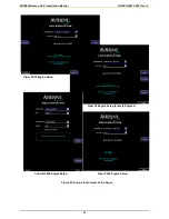
5.12.4 Long Range Tanks Setup
Some aircraft are equipped with long range fuel tanks. If the Long Range Fuel Tanks feature is
available on this aircraft, the
Long Range Tanks Installed?
checkbox will be available from the
Aircraft Setup Page. Check
Long Range Tanks Installed?
to allow the MFD to track long range fuel
usage.
5.12.5 Checklists Setup (Cirrus & Columbia Only)
EX5000 MFDs in Cirrus & Columbia aircraft support Checklists. If Checklists are available for this
aircraft, the Checklist pull-down will be available from the Aircraft Setup Page.
Use the Checklist pull-down to select the appropriate aircraft and serial number range. Checklists are
only available for aircraft listed in the Checklist pull-down.
Caution
: The checklist function is only authorized for use specifically with the aircraft
types that are listed on the Aircraft Setup page.
Do not select any aircraft type that
does not match the installation aircraft.
If the installation aircraft type is not listed as
a checklist option on the Aircraft Setup page, then the checklist function is not
available for that aircraft.
Selecting an inappropriate aircraft type can lead to
incorrect operation of the aircraft by the pilot
.
Note:
This option is only available with software part numbers 530-00117-000, 530-00130-000,
530-00148-000, 530-00162-000/002, 530-00180-100/200, 530-00195-100/110/210, 530-
00201-100/200, and 530-00235-100/200..
Note:
The current revision of the installed checklists will appear on the splash screen on restarting
the MFD. If you modify the Checklist settings in the Aircraft setup page, restart the MFD and
observe the splash screen to verify the current revision of the Checklist.
Note:
If you are using an OEM-supplied build of Checklist Loader, follow the instructions in the
manual, “Multi-Function Display Checklist Editor - User’s Guide” (600-00144-000, Latest
Revision).
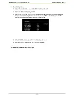
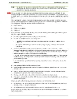
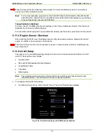
5.12.6 Dimming Bus Setup
On all aircraft, you can configure the LEDs on the bezel to better match the other cockpit instrument
lights on the aircraft dimming bus.
To set the dimming bus:
1.
Highlight the Brightest dimming voltage selection. An additional button,
Set Voltage,
appears
below the
Save
button.
2.
Adjust the Airplane dimming bus (usually a knob) to the full bright level. Monitor the dimming bus
voltage on the MFD below the selection boxes. When at full bright, press
Set Voltage
to update
the highlighted field.
3.
Highlight the Darkest dimming voltage selection and adjust the airplane dimming bus to a level so
that the other cockpit instruments are at their lowest brightness level.
4.
Press
Set Voltage
again to update the Darkest dimming voltage field.
5.12.7 Dimming Bus Checkout
Restart the MFD. Adjust the aircraft dimming bus and verify that the MFD bezel LEDs match the rest
of the cockpit instrument lamps and lights.
Содержание Entegra EX5000
Страница 1: ......
Страница 64: ...EX5000 Release 8 2 2 Installation Manual P N 600 00073 001 Rev 02 64 Save Configuration ...
Страница 95: ...EX5000 Release 8 2 2 Installation Manual P N 600 00073 001 Rev 02 95 Appendix G Landscape Cutout Dimensions ...
Страница 96: ...EX5000 Release 8 2 2 Installation Manual P N 600 00073 001 Rev 02 96 Appendix H Portrait Cutout Dimensions ...
Страница 98: ...EX5000 Release 8 2 2 Installation Manual P N 600 00073 001 Rev 02 98 Appendix J Wiring Diagram GPS FMS ...
Страница 99: ...EX5000 Release 8 2 2 Installation Manual P N 600 00073 001 Rev 02 99 ...
Страница 101: ...EX5000 Release 8 2 2 Installation Manual P N 600 00073 001 Rev 02 101 Appendix L Wiring Diagram Traffic Sensors ...
Страница 102: ...EX5000 Release 8 2 2 Installation Manual P N 600 00073 001 Rev 02 102 Appendix M Wiring Diagram TAWS ...
Страница 103: ...EX5000 Release 8 2 2 Installation Manual P N 600 00073 001 Rev 02 103 Appendix N Wiring Diagram Radar Sensor ...
Страница 104: ...EX5000 Release 8 2 2 Installation Manual P N 600 00073 001 Rev 02 104 Appendix O Wiring Diagram Engine Sensors ...


