


EX5000 Release 8.2.2 Installation Manual
- 66 -
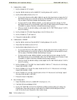
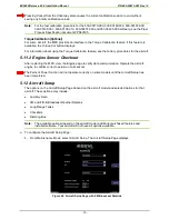
5.10.2 Roll Trim Adjustment
To adjust the Roll Trim Adjustment:
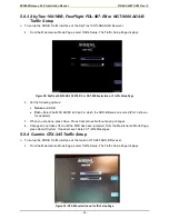
1.
From the Maintenance Mode Page, select
Setup Radar
.
2.
From the Radar Setup page. select
Roll Trim.
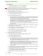
3.
The Roll Trim value appears on the Radar screen and can be modified by the Roll Trim control
knob.
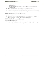
4.
When you are done, press
Back
to save the new Roll Trim setting and return to the Radar Setup
Page.
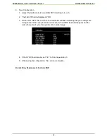
5.
Press
Save
from the Radar Setup Page. Press
Cancel
to exit without saving changes.
6.
Changes do not take effect until the MFD has been restarted. From the Maintenance Mode Page,
press
Restart System
.
5.10.3 RADAR Checkout
Perform a functional test of the RADAR system in accordance with manufacturers instructions. See
the
MFD Pilot Guide
for display operation.
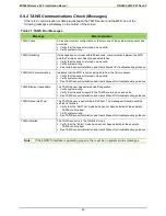
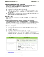
5.10.4 RADAR Sensor Communications Troubleshooting
If there is a communication or data error between the RADAR sensor and the MFD, one of the
following messages will display on the bottom of the screen.
Table 23: Radar Sensor Error Messages
Message
Meaning/Action
Radar Sensor Data Is Invalid
Data received from the RADAR sensor system can not be used by the
EX5000
Cycle power on the EX5000.
See RADAR Sensor Installation and User’s Manual for troubleshooting
guidance.
Radar Sensor Has Failed
The RADAR sensor system has reported an error.
Check R/T configuration module error log.
See the RADAR Sensor Installation and User’s Manual for
troubleshooting guidance.
Radar Sensor Is Not Communicating
Communication of return data from the RADAR sensor to the MFD has
been lost.
Verify that the RADAR sensor is turned on and valid.
Verify that the EX5000 is properly seat in its tray.
Verify system wiring.
Invalid GPS Data and Radar is ON
The RADAR is ON and the EX5000 has no ground speed data available
from the GPS/FMS.
Verify the GPS/FMS is ON and valid.
Verify system wiring.
See the RADAR Sensor Installation and User’s Manual for
troubleshooting guidance.
Radar Automatic Standby Disabled
The RADAR is ON, the EX5000 RADAR automatic standby mode is
disabled, and the EX5000 has no ground speed data available from the
GPS/FMS.
Verify the GPS/FMS is ON and valid.
Verify system wiring.
See the RADAR Sensor Installation and User’s Manual for
troubleshooting guidance.
Содержание Entegra EX5000
Страница 1: ......
Страница 64: ...EX5000 Release 8 2 2 Installation Manual P N 600 00073 001 Rev 02 64 Save Configuration ...
Страница 95: ...EX5000 Release 8 2 2 Installation Manual P N 600 00073 001 Rev 02 95 Appendix G Landscape Cutout Dimensions ...
Страница 96: ...EX5000 Release 8 2 2 Installation Manual P N 600 00073 001 Rev 02 96 Appendix H Portrait Cutout Dimensions ...
Страница 98: ...EX5000 Release 8 2 2 Installation Manual P N 600 00073 001 Rev 02 98 Appendix J Wiring Diagram GPS FMS ...
Страница 99: ...EX5000 Release 8 2 2 Installation Manual P N 600 00073 001 Rev 02 99 ...
Страница 101: ...EX5000 Release 8 2 2 Installation Manual P N 600 00073 001 Rev 02 101 Appendix L Wiring Diagram Traffic Sensors ...
Страница 102: ...EX5000 Release 8 2 2 Installation Manual P N 600 00073 001 Rev 02 102 Appendix M Wiring Diagram TAWS ...
Страница 103: ...EX5000 Release 8 2 2 Installation Manual P N 600 00073 001 Rev 02 103 Appendix N Wiring Diagram Radar Sensor ...
Страница 104: ...EX5000 Release 8 2 2 Installation Manual P N 600 00073 001 Rev 02 104 Appendix O Wiring Diagram Engine Sensors ...