


EX5000 Release 8.2.2 Installation Manual
- 48 -
Table 19: TCAD Shield Settings
Range (NM: 0.5)
Height (feet: 100)
Min
Max
Min
Max
Terminal
0.5
1.5
200
1000
Standard
1.0
3.0
500
1500
Enroute
2.0
6.0
1000
2000
Note:
The Max range values shown above are the largest values that the TCAD processor will
accept. Choosing larger values than those shown will cause the processor to default to
smaller shield sizes and is not recommended.
5.
When you are done, press
Save
. Press
Cancel
to exit without saving changes.
6.
Changes do not take effect until the MFD has been restarted. From the Maintenance Mode Page,
press
Restart System
. If needed, see Table 20: Traffic Messages.
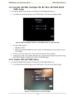
5.7.5 TCAD Dual Display Setup
When installing the MFD with an Avidyne TAS600 9900BX display unit, see the
Avidyne TAS600
Series Installation Manual
for wiring procedures. See Figure 2-15 Wiring Diagram for Dual Displays
and Section 7 in the Ryan manual for instructions.
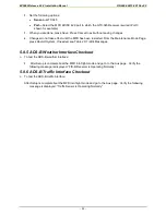
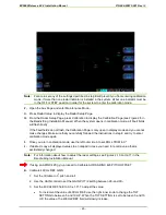
5.7.6 TCAD Checkout
The MFD does not display the TCAD Self Test function. To perform this test, use the Avidyne
TAS600 display unit.
•
On installations with the TCAD 9900 display unit, follow the checkout procedures shown in the
Avidyne TAS600 Series Installation Manual
.
•
On installations without the TCAD 9900 display unit (MFD only), follow the checkout procedures
shown in the
Avidyne TAS600 Series Installation Manual
with the exception of the display test.
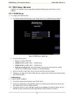
5.7.7 TIS-G Setup
The EX5000 optionally supports the display of traffic information from a Garmin GTX-330 TIS-capable
Mode-S transponder.
To set up the TIS Traffic Sensor:
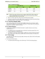
1.
From the Maintenance Mode Page, select Traffic Setup. The Traffic Setup Page displays:
Содержание Entegra EX5000
Страница 1: ......
Страница 64: ...EX5000 Release 8 2 2 Installation Manual P N 600 00073 001 Rev 02 64 Save Configuration ...
Страница 95: ...EX5000 Release 8 2 2 Installation Manual P N 600 00073 001 Rev 02 95 Appendix G Landscape Cutout Dimensions ...
Страница 96: ...EX5000 Release 8 2 2 Installation Manual P N 600 00073 001 Rev 02 96 Appendix H Portrait Cutout Dimensions ...
Страница 98: ...EX5000 Release 8 2 2 Installation Manual P N 600 00073 001 Rev 02 98 Appendix J Wiring Diagram GPS FMS ...
Страница 99: ...EX5000 Release 8 2 2 Installation Manual P N 600 00073 001 Rev 02 99 ...
Страница 101: ...EX5000 Release 8 2 2 Installation Manual P N 600 00073 001 Rev 02 101 Appendix L Wiring Diagram Traffic Sensors ...
Страница 102: ...EX5000 Release 8 2 2 Installation Manual P N 600 00073 001 Rev 02 102 Appendix M Wiring Diagram TAWS ...
Страница 103: ...EX5000 Release 8 2 2 Installation Manual P N 600 00073 001 Rev 02 103 Appendix N Wiring Diagram Radar Sensor ...
Страница 104: ...EX5000 Release 8 2 2 Installation Manual P N 600 00073 001 Rev 02 104 Appendix O Wiring Diagram Engine Sensors ...


