background image

AXP340 Transponder Installation Manual 


10 March 2014 

01201-00 


 Issue AF 


______________________ 

AVIDYNE CORPORATION 


iii 


5.5.4


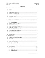
Altitude Inputs and Output ............................................................................................. 11


5.5.5


Squat Switch Input .......................................................................................................... 12


5.5.6


Ident Switch Input ........................................................................................................... 12


5.5.7


External Standby Input ................................................................................................... 12


5.5.8


Audio Output .................................................................................................................. 12


5.5.9


Altitude Alerter Output ................................................................................................... 13


5.5.10


GPS Position Input ......................................................................................................... 13


5.6


M

OLEX 

C

RIMP 

T

ERMINALS

 ...................................................................................................... 14


5.7


A

NTENNA 

I

NSTALLATION

......................................................................................................... 15


5.7.1


Antenna Cable ................................................................................................................ 15


5.7.2


BNC Connector ............................................................................................................... 17


5.8


T

RAY 

/


BNC


C

ONNECTOR 

A

SSEMBLY

 ..................................................................................... 19


6.


INSTALLATION SETUP AND TEST ....................................................................................... 20


6.1


C

ONFIGURATION 

I

TEMS

 ........................................................................................................... 20


6.1.1


Aircraft Registration ....................................................................................................... 20


6.1.2


Aircraft Address Programming ...................................................................................... 20


6.1.3


VFR Squawk Code .......................................................................................................... 21


6.1.4


Airspeed Category .......................................................................................................... 21


6.1.5


Aircraft Category ............................................................................................................ 21


6.1.6


Squat Switch Source ....................................................................................................... 21


6.1.7


GPS Input ....................................................................................................................... 21


6.1.8


GPS Line Speed .............................................................................................................. 21


6.1.9


GPS System Certification Level ...................................................................................... 21


6.1.10


GPS NACv ...................................................................................................................... 22


6.1.11


Aircraft Length and Width .............................................................................................. 22


6.1.12


GPS Antenna Offset ........................................................................................................ 22


6.1.13


ADS-B Receiver Options ................................................................................................. 22


6.1.14


Audio Volume ................................................................................................................. 22


6.1.15


Pressure Altitude Units ................................................................................................... 22


6.1.16


Lighting Control ............................................................................................................. 23


6.1.17


LCD Dim Point ............................................................................................................... 23


6.1.18


LCD Brightness .............................................................................................................. 23

 

6.2


T

EST ITEMS

 .............................................................................................................................. 23
 

6.2.1


Interface Check ............................................................................................................... 23
 

6.2.2


Altitude Check ................................................................................................................. 23
 

Содержание AXP340 MODE S

Страница 1: ...AXP340 MODE S TRANSPONDER INSTALLATION MANUAL ...

Страница 2: ...l support please contact Avidyne using the following information 888 723 7592 781 402 7592 techsupport avidyne com All materials copyrighted including images that represent this software Copyright 2013 Trig Avionics Limited Parts of this document Copyright 2013 Avidyne Corporation All rights reserved The latest installation manuals are available to authorized dealers on the web at www avidyne com ...

Страница 3: ...IONS IN TRAY 4 3 3 INSTALLATION APPROVAL 5 3 4 TSO FAILURE CONDITION CLASSIFICATION 5 3 5 NON TSO FUNCTIONS 5 4 UNIT AND ACCESSORIES SUPPLIED 6 4 1 AXP340 MODE S TRANSPONDER ITEMS 6 4 2 MOUNTING TRAY INSTALLATION KIT 6 4 3 DOCUMENTATION 6 4 4 REQUIRED ITEMS 6 5 INSTALLATION 8 5 1 UNPACKING AND INSPECTING EQUIPMENT 8 5 2 MOUNTING 8 5 3 COOLING REQUIREMENTS 8 5 4 ELECTRICAL CONNECTIONS 8 5 4 1 Prima...

Страница 4: ...OR ASSEMBLY 19 6 INSTALLATION SETUP AND TEST 20 6 1 CONFIGURATION ITEMS 20 6 1 1 Aircraft Registration 20 6 1 2 Aircraft Address Programming 20 6 1 3 VFR Squawk Code 21 6 1 4 Airspeed Category 21 6 1 5 Aircraft Category 21 6 1 6 Squat Switch Source 21 6 1 7 GPS Input 21 6 1 8 GPS Line Speed 21 6 1 9 GPS System Certification Level 21 6 1 10 GPS NACv 22 6 1 11 Aircraft Length and Width 22 6 1 12 GPS...

Страница 5: ...FR 27 8 8 FUNC 27 8 9 SELECTOR KNOB 27 8 10 NUMERIC BUTTONS 27 8 11 CLR 27 8 12 SQUAWK CODE ENTRY 27 8 13 FLIGHT TIMER 28 8 14 STOPWATCH 28 8 15 FLIGHT ID ENTRY 28 8 16 ALTITUDE MONITOR 28 8 17 ADS B MONITOR 28 8 18 ALERT MESSAGES 28 8 19 FAULT ANNUNCIATION 29 8 20 LOW TEMPERATURE OPERATION 29 9 CONTINUED AIRWORTHINESS 30 10 ENVIRONMENTAL QUALIFICATION FORM 31 11 ADS B COMPLIANCE 33 11 1 ADS B PAR...

Страница 6: ...anual 10 March 2014 01201 00 Issue AF ______________________ AVIDYNE CORPORATION v 12 INSTALLATION DRAWINGS 35 13 BASIC INTERCONNECT DIAGRAM 36 14 AVIDYNE EXCLUSIVE LIMITED WARRANTY AND LIMITATIONS ON LIABILITY37 15 SOFTWARE LICENSE 39 ...

Страница 7: ...AXP340 Transponder Installation Manual 10 March 2014 01201 00 Issue AF ______________________ vi AVIDYNE CORPORATION This page intentionally left blank ...

Страница 8: ...of this manual the software version identifier for the AXP340 is 3 8 and the FPGA version identifier is 110613a The software and FPGA versions are subject to change without notice 1 3 Changes from Previous Issue Updated section 4 to reflect the Avidyne part numbers and kit combinations Corrected version numbering for updated documents Added KT76C to the list of equivalent transponder trays Added s...

Страница 9: ...he reliable operation of the system that each aircraft has a distinct Mode S address The Mode S address is allocated by the registration authority for the aircraft and must be set when the AXP340 is installed 2 2 Interfaces At the rear the transponder has two Molex style connectors and a single antenna connector for blind mating with the corresponding connectors in the mounting tray The interfaces...

Страница 10: ...h 2014 01201 00 Issue AF AVIDYNE CORPORATION Page 3 Altitude alert output Output used to signal altitude deviations when optional altitude monitor function is used GPS Input Connection to a GPS supplying position input for ADS B position reporting ...

Страница 11: ...ry A in DO 160G Operating Temperature 25C to 70C Transmitter Frequency 1090MHz 1MHz Transmitter Power 240 Watts nominal 125 Watts minimum at antenna after allowing for 0 5dB connector losses and 1 5dB cable losses Transmitter Modulation 6M75 V1D Receiver Frequency 1030 MHz Receiver Sensitivity 74dBm 3dB 3 1 1 Approved Deviations The AXP340 ADS B function is certified to ETSO C166b which references...

Страница 12: ...on of the functions defined in paragraph 3 a of these TSO s are a major failure condition 3 5 Non TSO Functions The AXP340 Mode S Transponder contains the following non TSO functions Stopwatch and Flight Timer The transponder provides a simple stopwatch and flight timer function displayed on the front panel Altitude Monitor The Altitude Monitor activates an audio annunciator or annunciator light d...

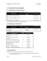
Страница 13: ...tems Unit Description Qty Manufacturer Part Number Avidyne Part Number Mounting Tray 1 01180 00 200 00258 000 Installation Kit 1 00223 00 The installation kit contains the following parts Unit Description Qty Part Number 12 way double sided crimp housing connector 1 00032 00 24 way double sided crimp housing connector 1 00033 00 Crimp Terminal Female 18 24 AWG 30 00236 00 Screw Pozidrive Pan Head ...

Страница 14: ...utput is recommended Cables You need to supply and fabricate all required cables Guidance on cable types is given in section 5 below Fixings To secure the transponder tray to the airframe you will need at least 6 flat head screws and six self locking nuts If the aircraft does not have existing mounting provisions you may need to fabricate additional brackets to support the transponder tray To supp...

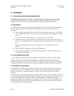
Страница 15: ...nsponder into the secured mounting tray Lock the AXP340 transponder into the mounting tray using a 3 32 Allen key taking care not to over tighten the locking screw 5 3 Cooling Requirements The AXP340 Mode S transponder meets all applicable ETSO requirements without forced air cooling Attention should however be given to the incorporation of cooling provisions to limit the maximum operating tempera...

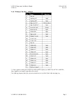
Страница 16: ...s In Input 10 Standby Switch Input 11 11 33V DC 12 11 33V DC A Ground B Altitude B4 Input C Altitude B2 Input D Altitude C1 Input E Altitude B1 Input F Ident Switch In Input H Altitude C4 Input J Altitude A4 Input K Altitude A2 Input L Altitude C2 Input M Altitude A1 Input N Do Not Connect These signals are different to the KT76A KT76C KT78A pinout on the KT76A KT76C and KT78A these signals are no...

Страница 17: ...4 3 Orientation Diagram To assist in connector orientation the following example shows a typical set of connections This diagram shows the expected connector positions when viewed from the transponder side of the tray looking into the tray from the front In the example shown the aircraft uses a 14 volt lighting bus a parallel altitude encoder a DME with simple suppression output a GPS with serial ...

Страница 18: ...pression allows two or more transmitters on adjacent frequencies to inhibit the other transmitters when one is active to limit the interference effects It is commonly used between transponders and DME systems and between transponders and collision avoidance systems The AXP340 provides two styles of mutual suppression interface on the 24 way connector The Suppress input on contact 9 is typically us...

Страница 19: ...parallel or serial for connection to a GPS or other equipment The serial output supplies RS232 output levels and runs at 9600 bps no parity The output format is always Icarus Trimble Garmin format If the altitude source is a parallel encoder the serial output is reported every 0 5 seconds if the source is a serial encoder the output simply repeats the input reports each report delayed by up to 10 ...

Страница 20: ...ector transistor and can sink up to 1 Amp DC The switched voltage should not exceed 60 Volts 5 5 10 GPS Position Input The GPS position input is required to support ADS B functionality The GPS position input is an RS232 input to the transponder The ADS B features are optional no GPS is required for normal Mode S Elementary Surveillance Specific GPS source and antenna and transponder combination mu...

Страница 21: ...ge depending on the intended airspace regulations For further information refer to Section 11 ADS B Compliance of this manual 5 6 Molex Crimp Terminals The Molex connector contacts should be wired with wire of 18 24 AWG The contacts are compatible with a wide range of crimp tools Ensure that the contact has been crimped using both the conductor crimp and the insulator crimp Once crimped the contac...

Страница 22: ... 1 Antenna Cable The AXP340 is designed to meet Class 1 requirements with an allowance of 2 dB for loss in the connectors and cable used to connect it to the antenna Excessive loss will degrade both transmitter output power and receiver sensitivity Allowing 0 25dB loss for the connector at each end of the antenna cable assembly leaves an allowance of 1 5dB maximum loss for the cable itself An acce...

Страница 23: ...r their data sheets When routing the cable ensure that you Route the cable away from sources of heat Route the cable away from potential interference sources such as ignition wiring 400Hz generators fluorescent lighting and electric motors Allow a minimum separation of 300mm 12 inches from an ADF antenna cable Keep the cable run as short as possible Avoid routing the cable round tight bends Avoid ...

Страница 24: ... 25 mm 1 inch of heat shrink tubing over the cable Dimension Cut size mm Cut size inches A 12 7 0 5 B 6 4 0 25 C 3 2 0 125 Insert the cable into the connector the inner conductor should align with the centre contact the inner shield should be inside the body of the connector and the outer shield should be outside the body Solder the centre conductor to the centre contact aligning the conductor wit...

Страница 25: ...00 Issue AF Page 18 AVIDYNE CORPORATION Slide heat shrink tubing forward flush to connector and heat to shrink the tubing Complete the assembly by installing the bushing over the centre contact and fitting the cap Solder the cap in place in at least two places ...

Страница 26: ...ng tray and attach the washer combination in the following order Wave washer p n 00317 00 Plain washer p n 00241 00 Circlip washer p n 00242 00 The Circlip washer should be fitted with a set of Circlip pliers The two Molex connectors should be passed through the openings in the rear of the tray and then mounted firmly to the tray from the inside using the four M3 screws supplied 00239 00 ...

Страница 27: ...g the selector knob accepts the current input Pressing the CLR back button allows you to change something you have already entered Rotating the selector knob moves up and down through the menu options Pressing the select tor knob or FUNC button accepts the selection and moves to the next screen 6 1 Configuration Items 6 1 1 Aircraft Registration Enter the aircraft registration using the numeric ke...

Страница 28: ...elector knob choose the aircraft category that most closely matches the aircraft in which the transponder is installed Press selector knob to accept and move to the next menu item 6 1 6 Squat Switch Source The Squat switch input allows the transponder to automatically switch between Airborne and Ground modes and to automatically start and stop the flight timer The sense of the squat switch input c...

Страница 29: ...ht operations this distinction is of no practical importance at all but if ADS B is used to manage taxiway conflicts a significant offset in antenna position could mean that the aircraft is not in the same place as the ADS B reported position Although primarily intended for position correction on large transport aircraft General Aviation aircraft can also have a significant offset For example if t...

Страница 30: ...ve the cockpit appearance Note it is only practical to do this in pitch darkness since that is the in flight environment that you are trying to reproduce If you are working in a hangar with any other lighting it may be better to leave the setting in the mid range 6 1 18 LCD Brightness The actual maximum brightness of the LCD cannot be increased with this control What it controls is the rate at whi...

Страница 31: ...onder is receiving data on the RS232 input Note that this check does not attempt to decode the received data it is intended only to provide a quick wiring check in the hangar To assure that the interface is fully operable the aircraft should be tested with the transponder in normal operating mode with the GPS receiver operating correctly and a ramp test of the transmitted parameters completed ...

Страница 32: ...matically to ALT Interrogations to verify the receiver sensitivity A Mode S transponder should have a minimum triggering level MTL of between 77 dBm and 71 dBm Failure to meet this requirement usually indicates antenna or coaxial cable problems Interrogations to verify the transmitted power A Class 1 installation should have no less than 125 Watts at the antenna and no more than 500 Watts Failure ...

Страница 33: ... atmospheric conditions apply this may not match the altimeter indicated altitude but will be correctly displayed by the ATC radar 8 4 POWER ON OFF Press the MODE button to turn on the transponder Hold the MODE button for at least 3 seconds to turn off the transponder A count down is displayed on the left side of the screen When the counter reaches zero and the screen turns off release the MODE bu...

Страница 34: ...or depending on installation altitude monitor and front panel dimming 8 9 Selector Knob The selector knob on the right side of the front panel is used to select data such as characters for Flight ID or move through the menu options Pressing the selector knob confirms the selection or selection of the options presented A label on the right side of the display describes the action when the selector ...

Страница 35: ... 8 16 Altitude Monitor The Altitude Monitor activates an audio annunciator or annunciator light depending on installation when the aircraft pressure altitude differs from the selected altitude by more than 200 feet Press the FUNC button to display the altitude monitor enable screen Pressing selector knob toggles the altitude monitor at the current altitude When altitude monitoring is in use ABOVE ...

Страница 36: ... detected Some FAULT indications can be recovered by switching the transponder off and back on again although in all cases a FAULT code implies that there is a fault with the transponder or the installation Note the FAULT message at the bottom of the screen and pass that information to your avionics maintenance organisation 8 20 Low Temperature Operation The AXP340 is certified to operate correctl...

Страница 37: ... manufactured to allow on condition maintenance This means that there are no periodic service requirements necessary to maintain continued airworthiness and no maintenance is required until the equipment does not properly perform its intended function When service is required a complete performance test should be accomplished following any repair action Repairs should only be carried out in accord...

Страница 38: ... Crash Safety 7 3 Equipment tested to Category B Vibration 8 0 Aircraft zone 2 type 3 4 5 to category S level M Equipment also tested to aircraft zone 2 type 1 Helicopters to category U level G Explosion 9 0 Equipment identified as Category X no test required Waterproofness 10 0 Equipment identified as Category X no test required Fluids Susceptibility 11 0 Equipment identified as Category X no tes...

Страница 39: ...nual 10 March 2014 01201 00 Issue AF Page 32 AVIDYNE CORPORATION Icing 24 0 Equipment identified as Category X no test required Electrostatic Discharge 25 0 Equipment tested to Category A Flammability 26 0 Equipment tested to Category C ...

Страница 40: ...0 5 Emergency Indicator 0 5 Barometric Altitude 0 5 Quality Indicator NIC 0 5 Airborne Position Latitude 0 5 Longitude 0 5 Quality Indicator NIC 0 6 Surface Position Latitude 0 6 Longitude 0 6 Surface Ground Speed 0 6 Surface Ground Track 0 6 Aircraft Identification 0 8 Airborne Ground Velocity 0 9 Geometric to Barometric Altitude Difference 0 9 Geometric Vertical Speed 0 9 Squawk Code 6 1 Emergen...

Страница 41: ...AXP340 Transponder Installation Manual 10 March 2014 01201 00 Issue AF Page 34 AVIDYNE CORPORATION ...

Страница 42: ...AXP340 Transponder Installation Manual 10 March 2014 01201 00 Issue AF AVIDYNE CORPORATION Page 35 12 Installation Drawings All dimensions in millimetres ...

Страница 43: ...erved RF 1 2 3 4 5 6 7 9 10 11 12 A F 8 B C D E H J K L M N 1 2 3 4 5 6 A B C D E F Coax GPS POSITION SOURCE MUTUALSUPPRESSIONBUS PARALLEL ALTITUDE ENCODER SERIAL ALTITUDE ENCODER or ADC 3A CIRCUIT BREAKER 11 33V TRANSPONDER ANTENNA 1 ALL WIRES SHOULD BE 18 24 AWG 2 ONLY CONNECT ONE ALTITUDE DATA SOURCE EITHER A SERIAL ENCODER PARALLEL ENCODER OR ADC NOTES 1 WHEN USING DATA FROM AN ADC IT SHOULD B...

Страница 44: ...rm applicable to the repaired or replaced Product or will be warranted under the warranty terms above for ninety days from the date of repair or replacement whichever period is longer THIS EXCLUSIVE LIMITED WARRANTY APPLIES IN LIEU OF AND EXPRESSLY SUPERCEDES AND EXCLUDES ALL OTHER REPRESENTATIONS AFFIRMATIONS AND OR WARRANTIES WHETHER EXPRESS OR IMPLIED ORAL OR WRITTEN INCLUDING WITHOUT LIMITATIO...

Страница 45: ...SSIBILITY THAT ANY DAMAGE MIGHT BE INCURRED ARISING OUT OF OR RELATED TO PRODUCTS NOT MANUFACTURED BY AVIDYNE THE PURCHASE OR SALE OF SUCH PRODUCTS THEIR PERFORMANCE OR RELIABILITY EITHER ALONE OR WHEN USED WITH ANY PRODUCT MANUFACTURED BY AVIDYNE OR THE SUITABILITY OF ANY SUCH PRODUCT FOR USE WITH ANY PRODUCT MANUFACTURED BY AVIDYNE THIS EXCLUSIVE LIMITED WARRANTY ALSO APPLIES IN LIEU OF AND EXPR...

Страница 46: ...ate expense and no part of them is in the public domain The Government acknowledges Avidyne s representation that the Software is Restricted Computer Software as that term is defined in Clause 52 227 19 of the Federal Acquisition Regulations FAR and is Commercial Computer Software as that term is defined in Subpart 227 401 of the Department of Defense Federal Acquisition Regulation Supplement DFAR...

Страница 47: ...terms and not those contained in your purchase order If you do not agree to the terms of this license Avidyne is unwilling to license the product to you In such event you may not use or copy the product and you should promptly contact Avidyne for instructions on return of the unused product s for a refund Copyright 2013 Trig Avionics Limited Parts of this document are 2013Avidyne Corporation All r...

Страница 48: ...AVIDYNE CORPORATION 55 Old Bedford Road Lincoln MA 01773 Telephone 781 402 7400 www avidyne com ...

Отзывы: