


Alarms, Errors, and Troubleshooting
555-233-143
4-24
Issue 1 May 2002
A short optical fiber jumper with connectors is required for this procedure. If the
link uses metallic cable, the metallic connector must be removed from behind the
carrier and a lightwave transceiver connected in its place.
Complete the following steps:
1. Note the condition of the amber LED on the circuit pack.
2. Busyout the circuit pack.
3. Disconnect the transmit and receive fiber pair from the lightwave
transceiver behind the circuit pack. Note which is the transmit fiber and
which is the receive fiber for proper re-connection at the end of this
procedure.
4. Connect the transmit and receive jacks of the lightwave transceiver with
the jumper cable.
NOTE:
Make sure that the total length of the fiber jumper cable does not
exceed the maximum length recommended for the fiber link
connections between cabinets. Otherwise, test results may be
influenced by violation of connectivity guidelines.
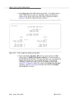
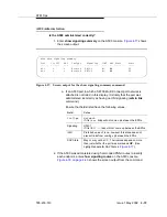
5. At the front of the cabinet, observe the amber LED on the looped back
circuit pack.
■
If the amber LED flashes once per second, the circuit pack or
transceiver should be replaced.
■
If the amber LED flashes five times per second, the circuit pack or
its lightwave transceiver may need replacement. This condition may
also be due to a faulty system clock on the port network (for an EI)
or the switch node carrier (for an SNI).
■
If the amber LED was flashing before starting this procedure, and it
is now either solid on or solid off, this circuit pack and its lightwave
transceiver are functioning properly.
6. Replace the faulty component(s) and reconnect the original cables in their
correct positions. Be sure to use a lightwave transceiver that matches the
one at the opposite end.
7. Release the circuit pack.
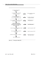
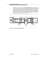
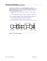
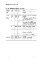
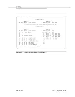
Loopback Tests for Isolating Fiber Faults
shows the loopbacks performed on the SNI circuit pack
for Tests #756 and #757. Test #756 reports the result of the off-board loopback;
Test #757 reports the result of the on-board loopback. Tests #756 and #757 can
run individually or as part of the test board UUCSS long command for an SNI
circuit pack.
Содержание S8700 Series
Страница 50: ...Maintenance Architecture 555 233 143 1 26 Issue 1 May 2002 ...
Страница 74: ...Initialization and Recovery 555 233 143 3 12 Issue 1 May 2002 ...
Страница 186: ...Alarms Errors and Troubleshooting 555 233 143 4 112 Issue 1 May 2002 ...
Страница 232: ...Additional Maintenance Procedures 555 233 143 5 46 Issue 1 May 2002 ...
Страница 635: ...status psa Issue 1 May 2002 7 379 555 233 143 status psa See status tti on page 7 406 ...
Страница 722: ...Maintenance Commands 555 233 143 7 466 Issue 1 May 2002 ...
Страница 1121: ...CARR POW Carrier Power Supply Issue 1 May 2002 8 399 555 233 143 Figure 8 19 Power Distribution Unit J58890CH 1 ...
Страница 1447: ...E DIG RES TN800 reserve slot Issue 1 May 2002 8 725 555 233 143 E DIG RES TN800 reserve slot See ASAI RES ...
Страница 1735: ...LGATE AJ Issue 1 May 2002 8 1013 555 233 143 LGATE AJ See BRI SET LGATE BD See BRI BD LGATE PT See BRI PT ...
Страница 1846: ...Maintenance Object Repair Procedures 555 233 143 8 1124 Issue 1 May 2002 Figure 8 62 TN787 MMI MULTIMEDIA INTERFACE CIRCUIT PACK ...