


TDM-BUS (TDM Bus)
Issue 1 May 2002
8-1589
555-233-143
TDM-Bus Fault Detection and Isolation
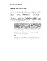
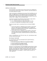
TDM-bus faults are usually caused by one of the following:
■
A defective circuit pack connected to the backplane
■
Bent pins on the backplane
■
Defective bus cables or terminators
It is possible that a circuit pack can cause a TDM-bus fault and still exhibit
trouble-free operation. For example, insertions of any circuit pack into a slot with
TDM bus terminations may bend the backplane pins and short two leads together.
Since the TDM bus is a shared resource, identification of the cause of a TDM-bus
fault can be difficult. If a TDM-bus problem is suspected, run the test tdm P
command. If any of the resulting tests fail, you must perform a manual TDM bus
isolation procedure to identify the cause of the problem.
!
WARNING:
Since the procedure for isolating TDM-bus faults involves removing circuit
packs and possibly disconnecting entire carriers, the procedure is extremely
destructive to the port network that contains the TDM bus being tested. If
possible, arrange to perform this procedure at a time when traffic is minimal.
As circuit packs are removed or entire carriers are disconnected, any active calls
terminating on those circuit packs or carriers will be dropped. If you have any
hints about a particular circuit pack that may be causing the TDM bus problem
investigate those before performing this procedure (for example, look at any
circuit packs that were inserted into the PN just before the TDM bus problem
appeared.
When straightening or replacing backplane pins in a carrier that contains a CFY1B
Current Limiter, power to the cabinet must be removed. When straightening or
replacing backplane pins in a carrier that does NOT contain a CFY1B Current
Limiter, power to that carrier must be shut off. Failure to follow this procedure may
result in damage to circuit packs and power supplies, and can be hazardous to the
technician.
NOTE:
Maintenance software requires TN748 or TN420 Tone Detector circuit pack
to test the TDM bus. Before starting these procedures, make sure that one
of these is installed in the port network being investigated.
Содержание S8700 Series
Страница 50: ...Maintenance Architecture 555 233 143 1 26 Issue 1 May 2002 ...
Страница 74: ...Initialization and Recovery 555 233 143 3 12 Issue 1 May 2002 ...
Страница 186: ...Alarms Errors and Troubleshooting 555 233 143 4 112 Issue 1 May 2002 ...
Страница 232: ...Additional Maintenance Procedures 555 233 143 5 46 Issue 1 May 2002 ...
Страница 635: ...status psa Issue 1 May 2002 7 379 555 233 143 status psa See status tti on page 7 406 ...
Страница 722: ...Maintenance Commands 555 233 143 7 466 Issue 1 May 2002 ...
Страница 1121: ...CARR POW Carrier Power Supply Issue 1 May 2002 8 399 555 233 143 Figure 8 19 Power Distribution Unit J58890CH 1 ...
Страница 1447: ...E DIG RES TN800 reserve slot Issue 1 May 2002 8 725 555 233 143 E DIG RES TN800 reserve slot See ASAI RES ...
Страница 1735: ...LGATE AJ Issue 1 May 2002 8 1013 555 233 143 LGATE AJ See BRI SET LGATE BD See BRI BD LGATE PT See BRI PT ...
Страница 1846: ...Maintenance Object Repair Procedures 555 233 143 8 1124 Issue 1 May 2002 Figure 8 62 TN787 MMI MULTIMEDIA INTERFACE CIRCUIT PACK ...


