background image

Issue 2 January 2008

131


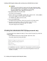
2. At the password prompt, enter the password. 

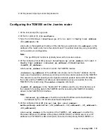
Configuring the TGM550 on the J-series router

1. At the root prompt (

%

), type 

cli

.

2. At the CLI prompt (

>

), type 

configure

.

3. Type the command 

set interfaces ge-0/0/

<x>

 unit 0 family inet address 

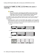
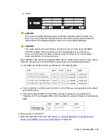
<IP_address1>/24

where 

<#>

 is the Gigabit port number of the interface you want and 

<IP_address1>

 is the 

address of the router, and 

/24

 is the subnet mask. The subnet mask may vary, depending 

on the customer’s configuration.

Note:

Note:

The ge-0/0/0 port number is typically reserved for services access.

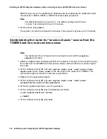
4. At the configure prompt (

#

), type 

set interfaces vp-

<slot_number>

/0/0 unit 0 

family inet address 

<internal_ip_address>/32


destination 

<tgm550_IP_address>

where 

<slot_number>

 is the slot in which the TGM550 resides.

<internal_ip_address>

 is the address, also known as the "source" address, 

that the 

router uses to establish a continuous point-to-point communication session to the TGM550. 
This session is used for passing control signals and data packets back and forth between 
the router and the TGM550 and allows an administration access connection from the 
TGM550 to the router using the 

session chassis

 command. 

<tgm550_IP_address>

 is the "destination" IP address used by any other devices over 

the network for sending data to the TGM550 and for accessing the TGM550, including 
access to the TGM550 CLI interface.

Note:

Note:

<internal_ip_address>

 should be a private IP address and should always 

be followed by the 

/32

 32-bit subnet mask designation.

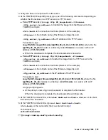
5. At the configure prompt (

#

), type 

set tgm fpc 

<slot_number>


media-gateway-controller [

<IP_address1>


<IP_address2>


<IP_address3> 

<IP_address4>

]

where 

<slot_number>

 is the location of the TGM550, 

<IP_address1>

 is either the 

Processor Ethernet IP address of the primary S8300, S8400, or S8500 server or an IP 
address to a TN799DP C-LAN circuit pack connected to the primary S8400, S8500, or 

Содержание IG550

Страница 1: ...Installing and Configuring the Avaya IG550 Integrated Gateway 03 601554 Issue 2 January 2008 ...

Страница 2: ...e extent made by the Customer or End User Link disclaimer Avaya Inc is not responsible for the contents or reliability of any linked Web sites referenced elsewhere within this documentation and Avaya does not necessarily endorse the products services or information described or offered within them We cannot guarantee that these links will work all of the time and we have no control over the availa...

Страница 3: ...nding cable 24 Connecting AC power 25 Connecting DC power 26 Inserting the Disk on Key 29 Turning on the Juniper Services Router 29 Cabling an Ethernet port on the Juniper Services Router 32 Connecting your PC or laptop to the console port on the J series router 33 Logging in to the Juniper Series Router 34 Administering the router for session chassis access from the TGM550 and non root services a...

Страница 4: ... 64 Configuring the TGM550 71 Configuring the WAN interface 73 Cabling an Ethernet port on the J series router 74 Connecting your PC or laptop to the console port on the J series router 74 Logging in to the Juniper Series Router 75 Logging in to the TGM550 76 Checking the MGC list transition points 76 Pinging the Communication Manager server 77 Updating TGM550 firmware if necessary 77 Checking the...

Страница 5: ...GM550 107 Checking the MGC list transition points 108 Pinging the Communication Manager server 108 Updating TGM550 firmware if necessary 109 Checking the authentication file ID Avaya personnel only 111 Connecting the USB modem 111 Configuring the USB modem for remote dial in 112 Additional configuration that might be needed 114 Chapter 5 Installing an IG550 Integrated Gateway with an existing Juni...

Страница 6: ...USB modem 137 Configuring the USB modem for remote dial in 137 Additional configuration that might be needed 140 Chapter 6 Administering Communication Manager on the server to support the IG550 Integrated Gateway 141 Accessing Communication Manager 141 Administering node names for C LAN circuit packs 8400 8500 87xx 141 Administering IP interfaces for C LAN circuit packs S8400 S8500 or S8700 series...

Страница 7: ...ort on the J series router 169 Rebooting the router and changing the root password 170 Recovering the root password of the TGM550 171 Retrieving the craft password of the TGM550 Avaya services personnel only 174 Restoring the old authentication file on a new TGM550 174 Appendix B Configuring your computer for J Web Quick Configuration access 177 Checking your version of windows 177 Changing TCP IP...

Страница 8: ...d Personnel Warning 188 Preventing Electrostatic Discharge Damage 188 Appendix D Removing and inserting TGM550 Field Replaceable Units 189 Ordering equipment 189 Replacing a VoIP module 189 Removing the TGM550 module 190 Removing a VoIP module 191 Inserting a VoIP module 191 Reinserting the TGM550 module 192 Index 193 ...

Страница 9: ...6350 Services Router on page 117 You or other personnel must also complete the following task Chapter 6 Administering Communication Manager on the server to support the IG550 Integrated Gateway on page 141 Note Note In most cases you administer Communication Manager on the server before you install the TGM550 and Juniper Services Router However you can also administer Communication Manager last To...

Страница 10: ...What procedure you should use 10 Installing and Configuring the IG550 Integrated Gateway ...

Страница 11: ... IG550 Integrated Gateway with the J Web Quick Configuration interface on page 45 Creating a Disk on Key You or a software engineer may need to create the Disk on Key The Disk on Key stores a configuration file that you generate with an Electronic Preinstallation Worksheet EPW for the Provisioning and Installation Manager PIM The EPW is available at http support avaya com Select FIND DOCUMENTATION...

Страница 12: ...irmware compatibility The software for the J series router must be release 8 4 or higher If it is not upgrade the router software to release 8 4 before continuing with the installation See the Juniper J2320 J2350 J4350 and J6350 Services Router Getting Started Guide Release 8 4 CAUTION CAUTION Neither the Telephony Interface Modules TIMs nor the TGM550 should be inserted into the J series router b...

Страница 13: ...u might be required to access the Download Center Web site to download firmware 1 Go to http www avaya com support 2 Navigate to Downloads The system displays a list of download categories 3 Select Latest TN Circuit Pack Server and Media Gateway Firmware and Software Updates 4 Locate the file name or file names that match the files listed in your planning documentation Note Note The firmware versi...

Страница 14: ...to the tftpboot directory on the S8300 Server Note Note Use a Linux based or a Unix based TFTP server only if the customer already has an existing one In these cases download the file to your laptop computer and give the file to the customer for proper placement and execution If the customer does not have a TFTP server or an FTP server you can use download a TFTP server to your laptop to use with ...

Страница 15: ...terface Modules TIMs and Physical Interface Modules PIMs CAUTION CAUTION You cannot use a 14 AWG grounding cable with the router The grounding cable must be 10 AWG An Avaya approved USB modem Two different sets of console cables and adapters An RJ 45 flat rollover cable and a DB 9 adapter for console connections to the TGM550 An ordinary round RJ 45 Ethernet cable and a DB 9 adapter for console co...

Страница 16: ...es representative or sales engineer has ordered the appropriate quantity and types of TIM and PIM modules for the router you are installing If the power required of the TIMs and PIMs has not yet been calculated see TIM and PIM limits based on heat and power used by the IG550 in Overview of the Avaya IG550 Integrated Gateway 03 601548 Installing the router in the rack 1 If the customer has a four p...

Страница 17: ...ighten all screws 4 Remove the bolts or screws in the resting holes Ga tew ay AL M AC T TG M5 50 Co ns ole AS B ET R RS T Lin e Tru nk 1 2 3 4 An alo g AL M AC T TIM 51 4 Lin e 5 6 7 8 Lin e 1 2 3 4 E1 T1 AL M AC T TIM 51 0 TS T SIG SO EI SM EM SI EO BR I AL M AC T TIM 52 1 4 3 2 1 CO NS OL E AU X US B 0 1 1 2 3 4 5 6 J4350 POWER PO WE R RE SE T CO NF IG STATUS ALARM HA 10 100 10 00 0 0 0 1 0 2 0 ...

Страница 18: ...02406 3marack Gate way ALM ACT TGM 550 Cons ole ASB ETR RST Line Trunk 1 2 3 4 Analo g ALM ACT TIM5 14 Line 5 6 7 8 Line 1 2 3 4 E1 T 1 ALM ACT TIM5 10 TST SIG SO EI SM EM SI EO BRI ALM ACT TIM5 21 4 3 2 1 CON SOLE AUX USB 0 1 1 2 3 4 5 6 J4350 POWER POW ER RES ET CON FIG STATUS ALARM HA 10 100 1000 0 0 0 1 0 2 0 3 LINK TX RX LINK TX RX LINK TX RX TX RX LINK Ju nip er NET WO RKS ...

Страница 19: ...w with the following steps 1 Determine the slots in which to insert the TGM550 TIMs and PIMs The slots must match the configuration you plan to set up on the Communication Manager server In addition the modules must be inserted according to limitations of the supported router models and slots Slot numbering on the routers is as follows J2320 J2350 J4350 hwma232s LAO 061407 CONSOLE AUX USB0 1 2 3 P...

Страница 20: ...llowing table The JX 1DS3 S 1 x DS3 and JX 1E3 S 1 x E3 PIMs are not supported on the J2320 and J2350 routers The 16 port GigaE uPIM 16 Port uPIM requires the space of two vertical slots Therefore the 16 port GigaE uPIM can be inserted into slots as indicated in the following table 2 Ensure power is turned off 3 Attach the blue filter inlet cover see Figure 12 Sample illustration of Juniper Servic...

Страница 21: ...s firmly in the router CAUTION CAUTION Carefully slide the module straight into the slot to avoid damaging the connector components 7 Drive the screws to hold the module in place Figure 3 Inserting the TGM550 and TIMs into the router 8 Retighten the screws on any blank faceplates that you loosened h LAO 100306 3macrdr Analog ALM ACT TIM 514 Line 5 6 7 8 Line 1 2 3 4 E1 T 1 ALM ACT TIM 510 TST SIG ...

Страница 22: ...ed by the local telephone company Analog voice terminals use one of the following types of combined over voltage and sneak current protection at the building entry point Gas tube with heat coil 4B1E W Solid state with heat coil 4C1S IROB 146C 4 lines or 146F 25 lines Avaya TIM521 ISDN BRI Media Module over voltage and sneak current protection are provided on the Media Modules Network side PSTN app...

Страница 23: ...to four BRI trunk connections For each trunk connection insert the CAT5 cable into an NT1 device Then connect the NT1 device to the 2 wire central office connection Juniper PIMs see Juniper J2320 J2350 J4350 and J6350 Services Router Getting Started Guide Release 8 4 2 Insert the cable connector into the port on the interface faceplate 3 For the TIM508 TIM516 or TIM518 use the screw at the end of ...

Страница 24: ... Be 10 AWG Able to handle up to 8 Amps amperage Have a ring type vinyl insulated TV14 6R lug or equivalent to accommodate the 10 AWG cable 1 Connect the grounding cable to an earth ground 2 Attach the lug on the cable to the chassis grounding point with the screw see Figure 4 Figure 5 or Figure 6 Figure 4 Grounding and power connections to the J4350 chassis Figure 5 Grounding and power connections...

Страница 25: ...ections to the J2320 chassis Figure 7 Grounding and power connections to the J2350 chassis Connecting AC power 1 Insert the appliance coupler end of a power cord into the appliance inlet on the power supply faceplate Figure 19 Figure 20 Figure 21 or Figure 22 ...

Страница 26: ...r hang where people might trip on the cord Connecting DC power 1 Use a voltmeter to measure the voltage across the DC power source cable leads Ensure that the voltage is 0 V and that the cable leads cannot become active during installation 2 Verify that a licensed electrician has attached the appropriate power cable lugs to the ends of the negative and the positive DC source power cables These cab...

Страница 27: ...Issue 2 January 2008 27 Figure 9 DC power connections to the 6350 chassis h LAO 100306 3magnd2 ...

Страница 28: ...els 48 VDC and RTN 5 Each screw contains a captive washer that you use to secure a DC source power cable lug to the terminal block 6 Use one of the removed screws to secure the positive DC source power cable lug to the RTN terminal 7 Use the other removed screw to secure the negative DC source power cable lug to the 48 VDC terminal 8 Dress the power cables appropriately 9 Replace the clear plastic...

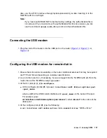
Страница 29: ...ices Router 1 Press the power button to turn on the Juniper Services Router Figure 12 Figure 13 Figure 14 h LAO 082606 3mausbk Gatew ay ALM ACT TGM55 0 Con so le ASB ETR RST Line Trun k 1 2 3 4 Ana log ALM ACT TIM 51 4 Line 5 6 7 8 Line 1 2 3 4 E1 T1 ALM ACT TIM 51 0 TST SIG SO EI SM EM SI EO BRI ALM ACT TIM 52 1 4 3 2 1 CONSOLE AUX USB 0 1 1 2 3 4 5 6 J4350 POWER POW ER RESET CONFIG STATUS ALARM ...

Страница 30: ...interface module 8 TIM510 E1 T1 telephony interface module 9 Juniper Router Alarm LEDs 10 Juniper Router Power LEDs 11 Power button 12 Reset button 13 Gigabit Ethernet ports 14 Console port 15 Aux port 16 USB ports 2 3 4 5 6 h LAO 082406 3mafrnt Gateway ALM ACT TGM550 Console ASB ETR RST Line Trunk 1 2 3 4 Analog ALM ACT TIM514 Line 5 6 7 8 Line 1 2 3 4 E1 T1 ALM ACT TIM510 TST SIG SO EI SM EM SI ...

Страница 31: ...e 11 TGM550 Telephony Gateway Module 12 Dual port T1 physical interface module 13 TIM510 E1 T1 telephony interface module hwma235c LAO 041907 Gateway ALM ACT TGM550 Console ASB ETR RST Line Trunk 1 2 3 4 Analog ALM ACT TIM514 Line 5 6 7 8 Line 1 2 3 4 CONSOLE AUX USB0 1 2 3 4 5 J2350 POWER POWER RESET CONFIG STA TUS ALARM HA 10 100 1000 0 0 0 1 0 2 0 3 LINK TX RX LINK TX RX LINK TX RX TX RX LINK J...

Страница 32: ...e into one of the Gigabit Ethernet ports on the router Figure 12 Figure 13 Figure 14 2 Attach the other end of the cable to the LAN Figure notes 1 Juniper Router Alarm LEDs 2 Juniper Router Power LEDs 3 Power button 4 Reset button 5 Console port 6 Aux port 7 Gigabit Ethernet ports 8 USB ports 9 TIM514 analog telephony interface module 10 TGM550 Telephony Gateway Module 11 Dual port T1 Physical Int...

Страница 33: ...ect the other end of the Ethernet rollover cable to the console port on the router Figure 15 3 Turn on the power to the personal computer Start Microsoft Windows Hyperterminal or another asynchronous terminal emulation application Select the appropriate COM port to use such as COM1 4 Configure the port settings as follows Bits per second 9600 Data bits 8 h LAO 082606 3malapa Ga tew ay AL M AC T TG...

Страница 34: ...y you can login without a password Just press Enter However you must set a new password before you commit the configuration Check with your Project Manager to get the password If you need to reset the password go to password recovery procedure at http www juniper net techpubs software jseries junos83 jseries83 admin guide user auth recover root pwd section html You can also reset the password by p...

Страница 35: ...s 5 At the configure prompt type set system login user user_name authentication plain text password 6 At the two password prompts enter the password 7 At the configure prompt type the following commands set system services telnet commit 8 At the configure prompt type exit Logging in to the TGM550 1 At the cli prompt type ssh login ip_address where login is root or another valid login if previously...

Страница 36: ...ow system 2 Note the serial number of the TGM550 You need the serial number later to administer the media gateway in Communication Manager See Adding Media Gateways on page 150 Checking the MGC list transition points 1 At the TGM550 command line type show recovery and check the transition points for the MGC list Pinging the Communication Manager server 1 At the TGM550 command line prompt type ping...

Страница 37: ...NOS software CAUTION CAUTION Update firmware on the TGM550 before you update JUNOS software on the J series router The newer TGM550 firmware can normally operate with older JUNOS software but older TGM550 firmware may not be able to operate with new JUNOS software 1 At the TGM550 00 super prompt type show boot bank to determine the nonactive disk partition or bank You copy the firmware to this non...

Страница 38: ... the firmware image file and ftp_server_ip_address is the IP address of the FTP server For example type copy ftp SW_imageA firmware tgm550_26_26_0 bin 195 123 49 54 where the file tgm550_26_26_ bin resides in a directory called firmware on a server with an IP address of 195 123 49 54 A login prompt appears a At the prompt enter a login and password to complete the file transfer When the download i...

Страница 39: ...ware Checking the authentication file ID Avaya personnel only The authentication file is installed at the factory To retrieve the AF ID product ID perform the following steps 1 At the TGM550 command line prompt type show auth file info The system displays the following information 2 In the AF ID field record the 10 digit AF ID In the example the AF ID is 7000003638 3 Use the AF ID to register the ...

Страница 40: ...are FTP and Telnet depending on customer specifications 2 Log in to the router CLI if necessary If you are logged into the TGM550 with ssh from the router then at the TGM550 prompt type exit 3 At the CLI prompt type configure At the configure prompt type set interfaces umd0 dialer options pool pool_name where umd0 is the USB modem interface and pool_name is the name of the pool For example type se...

Страница 41: ...e the same name as the access_profile_name such that remote dial in from other domains can use the same chap secrets of the access profile For example type set interfaces dl1 unit 0 ppp options chap local name jtr where a calling host computer from outside the router domain also uses the chap secret assigned to profile jtr set interfaces dl unit 0 dialer options pool pool where is the number from ...

Страница 42: ...ddress over the umd0 modem interface For example type set interfaces dl1 unit 0 family inet address 10 6 151 249 30 destination 10 6 151 250 where dialer 1 uses 10 6 151 249 as the incoming IP address from the modem interface and sends 10 6 151 250 as the outgoing IP address set access profile access_profile_name client client_name chap secret chap_secret_string where access_profile_name is the na...

Страница 43: ... the extent to which the router is configured The following configuration items are mandatory and will always be included in the configuration file Router Gigabit Ethernet address TGM550 IP address and slot number vp or TGM550 interface address which is used for communication between the router and the TGM550 Media Gateway Controller MGC list Root user password Other items that the file might also...

Страница 44: ... gateway IP address Loopback interface address Additional Fast Ethernet ports Serial port Additional Gigabit Ethernet ports To administer WAN and security features on the router to support the IG550 voice applications see the following documents as appropriate available at http juniper net J2320 J2350 J4350 and J6350 Services Router Getting Started Guide Release 8 4 J series Services Router Basic ...

Страница 45: ...er software to release 8 4 before continuing with the installation See the Juniper J2320 J2350 J4350 and J6350 Services Router Getting Started Guide Release 8 4 CAUTION CAUTION Neither the Telephony Interface Modules TIMs nor the TGM550 should be inserted into the J series router before you are sure the router is running release 8 4 or higher Failure to comply with this caution may cause your syst...

Страница 46: ...es listed in your planning documentation Note Note The firmware version of a file must match the hardware vintage or the release of Communication Manager or both and or the software of the Juniper Services Router See the Communication Manager Software Firmware Compatibility Matrix under Downloads on support avaya com 5 Double click each file name you want The system displays a File Download window...

Страница 47: ...e upgrades Reviewing safety requirements 1 See General Safety Guidelines and Warnings on page 187 Verifying equipment 1 Verify that you have the following on site Electrostatic discharge ESD grounding strap not provided For rack or wall installation flathead and Phillips head screwdrivers appropriate for the screws or anchors not provided For the Communication Manager server a license enabled for ...

Страница 48: ...ions to the Juniper router CAUTION CAUTION The two DB 9 adapters look the same but they are not Do not use the router adapter nor the Ethernet cable to connect to the TGM550 Additionally do not use the TGM550 adapter nor its rollover cable to connect to the router If you use the wrong cable or adapter you may damage the console port As a result it is strongly recommended that you use a permanent m...

Страница 49: ... required of the TIMs and PIMs has not yet been calculated see TIM and PIM limits based on heat and power used by the IG550 in Overview of the Avaya IG550 Integrated Gateway 03 601548 Installing the router in the rack 1 If the customer has a four post rack and is using a shelf install the shelf according to manufacturer guidelines Set the router on the shelf 2 If the customer is using the brackets...

Страница 50: ...ws and bottom screws in the mounting bracket into the rack Tighten all screws 4 Remove the bolts or screws in the resting holes Ga tew ay AL M AC T TG M5 50 Co ns ole AS B ET R RS T Lin e Tru nk 1 2 3 4 An alo g AL M AC T TIM 51 4 Lin e 5 6 7 8 Lin e 1 2 3 4 E1 T1 AL M AC T TIM 51 0 TS T SIG SO EI SM EM SI EO BR I AL M AC T TIM 52 1 4 3 2 1 CO NS OL E AU X US B 0 1 1 2 3 4 5 6 J4350 POWER PO WE R ...

Страница 51: ... ASB ETR RST Line Trunk 1 2 3 4 Analo g ALM ACT TIM5 14 Line 5 6 7 8 Line 1 2 3 4 E1 T 1 ALM ACT TIM5 10 TST SIG SO EI SM EM SI EO BRI ALM ACT TIM5 21 4 3 2 1 CON SOLE AUX USB 0 1 1 2 3 4 5 6 J4350 POWER POW ER RES ET CON FIG STATUS ALARM HA 10 100 1000 0 0 0 1 0 2 0 3 LINK TX RX LINK TX RX LINK TX RX TX RX LINK Ju nip er NET WO RKS ...

Страница 52: ...ed separately from the router insert them into the router now with the following steps 1 Determine the slots in which to insert the TGM550 TIMs and PIMs The slots must match the configuration you plan to set up on the Communication Manager server In addition the modules must be inserted according to limitations of the supported router models and slots Slot numbering on the routers is as follows J2...

Страница 53: ... 1 x E3 PIMs are not supported on the J2320 and J2350 routers The 16 port GigaE uPIM 16 Port uPIM requires the space of two vertical slots Therefore the 16 port GigaE uPIM can be inserted into slots as indicated in the following table 2 Ensure power is turned off 3 Attach the blue filter inlet cover see Figure 12 Sample illustration of Juniper Service Router and TGM550 front view J4350 shown on pa...

Страница 54: ... slot in the router Then slide the module in until it lodges firmly in the router CAUTION CAUTION Carefully slide the module straight into the slot to avoid damaging the connector components 7 Drive the screws to hold the module in place Figure 18 Inserting the TGM550 and TIMs into the router 8 Retighten the screws on any blank faceplates that you loosened h LAO 100306 3macrdr Analog ALM ACT TIM 5...

Страница 55: ...erminals use one of the following types of combined over voltage and sneak current protection at the building entry point Gas tube with heat coil 4B1E W Solid state with heat coil 4C1S IROB 146C 4 lines or 146F 25 lines Avaya TIM521 ISDN BRI Media Module over voltage and sneak current protection are provided on the Media Modules Network side PSTN applications require an NT 1 device Tie trunk appli...

Страница 56: ... pinouts TIM521 A CAT5 cable with an RJ45 connector for one to four BRI trunk connections For each trunk connection insert the CAT5 cable into an NT1 device Then connect the NT1 device to the 2 wire central office connection Juniper PIMs see Juniper J2320 J2350 J4350 and J6350 Services Router Getting Started Guide Release 8 4 2 Insert the cable connector into the port on the interface faceplate 3 ...

Страница 57: ...e a ring type vinyl insulated TV14 6R lug or equivalent to accommodate the 10 AWG cable 1 Connect the grounding cable to an earth ground 2 Attach the lug on the cable to the chassis grounding point with the screw see Figure 19 Figure 20 or Figure 21 Figure 19 Grounding and power connections to the J4350 chassis Figure 20 Grounding and power connections to the J6350 chassis ...

Страница 58: ...IG550 Integrated Gateway Figure 21 Grounding and power connections to the J2320 chassis Figure 22 Grounding and power connections to the J2350 chassis Connecting AC power 1 Insert the appliance coupler end of a power cord into the appliance inlet on the power supply faceplate Figure 19 Figure 20 Figure 21 or Figure 22 ...

Страница 59: ...cting DC power 1 Use a voltmeter to measure the voltage across the DC power source cable leads Ensure that the voltage is 0 V and that the cable leads cannot become active during installation 2 Verify that a licensed electrician has attached the appropriate power cable lugs to the ends of the negative and the positive DC source power cables These cable lugs are the lugs that you attach to the chas...

Страница 60: ...ling an IG550 Integrated Gateway with the J Web Quick Configuration interface 60 Installing and Configuring the IG550 Integrated Gateway Figure 24 DC power connections to the 6350 chassis h LAO 100306 3magnd2 ...

Страница 61: ...ve washer that you use to secure a DC source power cable lug to the terminal block 6 Use one of the removed screws to secure the positive DC source power cable lug to the RTN terminal 7 Use the other removed screw to secure the negative DC source power cable lug to the 48 VDC terminal 8 Dress the power cables appropriately 9 Replace the clear plastic cover over the terminal block 10 Verify that th...

Страница 62: ...s of the port that you connect to the router is set to 192 168 1 2 on the 192 168 1 1 24 subnetwork See Appendix B Configuring your computer for J Web Quick Configuration access on page 177 2 Turn off the power to your computer 3 Plug one end of the Ethernet cable into the Ethernet port on your computer 4 Connect the other end of the Ethernet cable to LAN PORT 0 on the router Figure 26 Laptop conn...

Страница 63: ...k with your Project Manager to get the password If you need to reset the password go to password recovery procedure at http www juniper net techpubs software jseries junos83 jseries83 admin guide user auth recover root pwd section html You can also reset the password by pressing the reset configuration button for twelve seconds However this method also overwrites any configuration data you may hav...

Страница 64: ...of the router Domain Name Optional Type the domain name of the router Root Password Type the root password CAUTION CAUTION If you were not prompted for a password when logging in you must assign a root password during the initial configuration Verify Root Password Retype the root password Time Zone From the drop down menu select the time zone for the router NTP Servers In the box that is next to t...

Страница 65: ...ay Type the IP address of the default gateway through which to direct packets that are addressed to networks that the routing table does not explicitly list Loopback Address Type the loopback address which is a reserved IP address that is always available on the router If you do not enter an address this address is set to 127 0 0 1 32 ge 0 0 0 0 Address Type the main IP address for access of the s...

Страница 66: ...Installing an IG550 Integrated Gateway with the J Web Quick Configuration interface 66 Installing and Configuring the IG550 Integrated Gateway 3 Click OK The J Web Summary List appears ...

Страница 67: ...Issue 2 January 2008 67 4 From the Summary list click Interfaces The Interfaces screen appears ...

Страница 68: ...ay with the J Web Quick Configuration interface 68 Installing and Configuring the IG550 Integrated Gateway 5 From the list in the Interface Name column click the appropriate ge interface The Interfaces screen for the ge interface appears ...

Страница 69: ...mation screen appears 7 In the box immediately above the Add button type the IP address of the ge interface In the box to the right of the slash type the CIDR subnet mask notation for example 24 8 Click Add The box for the IPv4 Addresses and Prefixes field displays the address you just added for example 134 33 22 56 24 ...

Страница 70: ...ted Gateway with the J Web Quick Configuration interface 70 Installing and Configuring the IG550 Integrated Gateway 9 Click OK The Interfaces screen appears again 10 At the bottom of the Interfaces screen click Apply 11 Click OK ...

Страница 71: ...2 January 2008 71 Configuring the TGM550 1 On the left navigation pane select Quick Configuration Interfaces The Interfaces screen appears 2 Click the vp 1 0 0 interface name The VoIP Interface screen appears ...

Страница 72: ...C List type the IP address of the primary controller or a C LAN circuit card that is connected to the primary controller Click Add Note Note Use commands on the TGM550 CLI to administer the transition point and recovery timer for the operation of the MGC list The default transition point value is 1 The default primary search time is 1 minute The total search time is 30 minutes 6 Repeat Step 5 for ...

Страница 73: ...s an administration access connection from the TGM550 to the router using the session chassis command Note Note internal_ip_address should be a private IP address and should always be followed by the 32 32 bit subnet mask designation 10 In the Destination Address field type the destination IP address which is used by any other devices over the network for sending data to the TGM550 and for accessi...

Страница 74: ...mmand line interface CLI Plug one end of an Ethernet rollover cable into the RJ 45 to DB 9 serial port adapter Figure 27 Note Note Use the specific cable and adapter for the router You cannot use the cable and the adapter that comes with the TGM550 Figure 27 Console adapter cable and port connections h LAO 082606 3malapa Ga tew ay AL M AC T TG M5 50 Co ns ole AS B ET R RS T Lin e Tru nk 1 2 3 4 An...

Страница 75: ...of the following a Press Enter No password is usually required at the first login b Enter a password The password might already be set if a staging process is used before the installation In this case your project manager must give you this password You are now logged in at the UNIX command line CAUTION CAUTION If a password is not already set you must set a new password before you commit the conf...

Страница 76: ...re you sure you want to continue connecting appears 2 Enter yes 3 At the password or challenge prompt type the password and press Enter You are now logged in If you are prompted to change the root password change the password to a password agreed upon with the customer administrator Tip Tip After a specific user login and password have been administered on the TGM550 you can alternatively use the ...

Страница 77: ...scroll down the screen 3 If the router does not successfully ping the server review the configuration using the following commands a At the CLI command line type show configuration display set and press Enter b Review the configuration with the project manager or customer to ensure the IP addresses are correct Updating TGM550 firmware if necessary Perform this task if the TGM550 firmware that resi...

Страница 78: ... is the IP address of the TFTP server For example type copy tftp SW_imageA firmware tgm550_26_26_0 bin 195 123 49 54 where the file tgm550_26_26_0 bin resides in a directory called firmware on a server with an IP address of 195 123 49 54 a When the download is complete the download status shows idle For an FTP server type copy ftp SW_image bank filename ftp_server_ip_address to transfer the image ...

Страница 79: ... last copy running config start config command was run 8 Type exit to return to the CLI of the router The Juniper CLI prompt appears 9 At the CLI prompt type request chassis fpc restart slot slot_number where slot_number is the slot number of the TGM550 The TGM550 media gateway processor resets 10 Log in to the TGM550 again The software banner that scrolls on the screen shows the new firmware vers...

Страница 80: ...rieve the appropriate password if you later must log in to the TGM550 with the craft login Note Note If you must use NVRAM INIT to restore factory settings the authentication file is not removed If you must remove the authentication file for some reason you can use the command erase auth file to remove the authentication file Connecting the USB modem 1 Plug the cord of the modem into the USB port ...

Страница 81: ... 149 for the dialer and access_profile_name is the name of the access profile that will contain a chap secret for the ppp dial in The dialer can apply to incoming outgoing or both dialing options for communication to the hosts listed in the profile For example type set interfaces dl1 unit 0 ppp options chap access profile jtr where the dialer is dialer 1 and the access profile name jtr to which th...

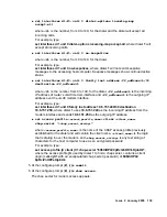
Страница 82: ...map accept all where is the number from 0 to 149 for the dialer and the dialer will accept all incoming calls For example type set interfaces dl1 unit 0 dialer options incoming map accept all where dialer 1 will accept all incoming calls set interfaces dl unit 0 no keepalives where is the number from 0 to 149 for the dialer For example type set interfaces dl1 unit 0 no keepalives where dialer 1 wi...

Страница 83: ...d of 9 XiHPQ 9pRclZntOIYeKjobUk 5 At the configure prompt type commit 6 At the configure prompt type show access The chap secret for modem access appears Note Note To complement the USB modem setup for remote dial in you must turn off IP compression on the computer you are using to remotely access the modem See Administration Guide and CLI Reference for the Avaya IG550 Integrated Gateway 03 601883...

Страница 84: ...o support the IG550 voice applications see the following documents as appropriate available at http juniper net J2320 J2350 J4350 and J6350 Services Router Getting Started Guide Release 8 4 J series Services Router Basic LAN and WAN Access Configuration Guide Release 8 4 J series Services Router Advanced WAN Access Configuration Guide Release 8 4 J series Services Router Administration Release 8 4...

Страница 85: ...to release 8 4 before continuing with the installation See the Juniper J2320 J2350 J4350 and J6350 Services Router Getting Started Guide Release 8 4 CAUTION CAUTION Neither the Telephony Interface Modules TIMs nor the TGM550 should be inserted into the J series router before you are sure the router is running release 8 4 or higher Failure to comply with this caution may cause your system to become...

Страница 86: ...r planning documentation Note Note The firmware version of a file must match the hardware vintage or the release of Communication Manager or both and or the software of the Juniper Services Router See the Communication Manager Software Firmware Compatibility Matrix under Downloads on support avaya com 5 Double click each file name you want The system displays a File Download window 6 Click Save th...

Страница 87: ...e upgrades Reviewing safety requirements 1 See General Safety Guidelines and Warnings on page 187 Verifying equipment 1 Verify that you have the following on site Electrostatic discharge ESD grounding strap not provided For rack or wall installation flathead and Phillips head screwdrivers appropriate for the screws or anchors not provided For the Communication Manager server a license enabled for ...

Страница 88: ...per router CAUTION CAUTION The two DB 9 adapters look the same but they are not Do not use the router adapter nor the Ethernet cable to connect to the TGM550 Additionally do not use the TGM550 adapter nor its rollover cable to connect to the router If you use the wrong cable or adapter you may damage the console port As a result it is strongly recommended that you use a permanent marker to label t...

Страница 89: ...er Services Router must match the firmware version of the TGM550 See the Communication Manager Software Firmware Compatibility Matrix under Downloads on http support avaya com 1 See the Juniper J2320 J2350 J4350 and J6350 Services Router Getting Started Guide Release 8 4 Installing the router in the rack 1 If the customer has a four post rack and is using a shelf install the shelf according to man...

Страница 90: ...Use the resting hole to temporarily hold the chassis 3 Place the top screws and bottom screws in the mounting bracket into the rack Tighten all screws 4 Remove the bolts or screws in the resting holes Ga tew ay AL M AC T TG M5 50 Co ns ole AS B ET R RS T Lin e Tru nk 1 2 3 4 An alo g AL M AC T TIM 51 4 Lin e 5 6 7 8 Lin e 1 2 3 4 E1 T1 AL M AC T TIM 51 0 TS T SIG SO EI SM EM SI EO BR I AL M AC T T...

Страница 91: ... ASB ETR RST Line Trunk 1 2 3 4 Analo g ALM ACT TIM5 14 Line 5 6 7 8 Line 1 2 3 4 E1 T 1 ALM ACT TIM5 10 TST SIG SO EI SM EM SI EO BRI ALM ACT TIM5 21 4 3 2 1 CON SOLE AUX USB 0 1 1 2 3 4 5 6 J4350 POWER POW ER RES ET CON FIG STATUS ALARM HA 10 100 1000 0 0 0 1 0 2 0 3 LINK TX RX LINK TX RX LINK TX RX TX RX LINK Ju nip er NET WO RKS ...

Страница 92: ...om the router insert them into the router now with the following steps 1 Determine the slots in which to insert the TGM550 TIMs and PIMs The slots must match the configuration you plan to set up on the Communication Manager server In addition the modules must be inserted according to limitations of the supported router models and slots Slot numbering on the routers is as follows J2320 J2350 J4350 ...

Страница 93: ... 1 x E3 PIMs are not supported on the J2320 and J2350 routers The 16 port GigaE uPIM 16 Port uPIM requires the space of two vertical slots Therefore the 16 port GigaE uPIM can be inserted into slots as indicated in the following table 2 Ensure power is turned off 3 Attach the blue filter inlet cover see Figure 12 Sample illustration of Juniper Service Router and TGM550 front view J4350 shown on pa...

Страница 94: ...ter Then slide the module in until it lodges firmly in the router CAUTION CAUTION Carefully slide the module straight into the slot to avoid damaging the connector components 7 Drive the screws to hold the module in place Figure 30 Inserting the TGM550 and TIMs into the router 8 Retighten the screws on any blank faceplates that you loosened h LAO 100306 3macrdr Analog ALM ACT TIM 514 Line 5 6 7 8 ...

Страница 95: ...erminals use one of the following types of combined over voltage and sneak current protection at the building entry point Gas tube with heat coil 4B1E W Solid state with heat coil 4C1S IROB 146C 4 lines or 146F 25 lines Avaya TIM521 ISDN BRI Media Module over voltage and sneak current protection are provided on the Media Modules Network side PSTN applications require an NT 1 device Tie trunk appli...

Страница 96: ...A CAT5 cable with an RJ45 connector for one to four BRI trunk connections For each trunk connection insert the CAT5 cable into an NT1 device Then connect the NT1 device to the 2 wire central office connection Juniper PIMs see Juniper J2320 J2350 J4350 and J6350 Services Router Getting Started Guide Release 8 4 2 Insert the cable connector into the port on the interface faceplate 3 For the TIM508 T...

Страница 97: ...e a ring type vinyl insulated TV14 6R lug or equivalent to accommodate the 10 AWG cable 1 Connect the grounding cable to an earth ground 2 Attach the lug on the cable to the chassis grounding point with the screw see Figure 31 Figure 32 or Figure 33 Figure 31 Grounding and power connections to the J4350 chassis Figure 32 Grounding and power connections to the J6350 chassis ...

Страница 98: ... Gateway Figure 33 Grounding and power connections to the J2320 chassis Figure 34 Grounding and power connections to the J2350 chassis Connecting AC power 1 Insert the appliance coupler end of a power cord into the appliance inlet on the power supply faceplate Figure 19 Figure 20 Figure 21 or Figure 22 ...

Страница 99: ...cting DC power 1 Use a voltmeter to measure the voltage across the DC power source cable leads Ensure that the voltage is 0 V and that the cable leads cannot become active during installation 2 Verify that a licensed electrician has attached the appropriate power cable lugs to the ends of the negative and the positive DC source power cables These cable lugs are the lugs that you attach to the chas...

Страница 100: ...Installing an IG550 Integrated Gateway with the CLI 100 Installing and Configuring the IG550 Integrated Gateway Figure 36 DC power connections to the 6350 chassis h LAO 100306 3magnd2 ...

Страница 101: ...ive washer that you use to secure a DC source power cable lug to the terminal block 6 Use one of the removed screws to secure the positive DC source power cable lug to the RTN terminal 7 Use the other removed screw to secure the negative DC source power cable lug to the 48 VDC terminal 8 Dress the power cables appropriately 9 Replace the clear plastic cover over the terminal block 10 Verify that t...

Страница 102: ...le into the RJ 45 to DB 9 serial port adapter Figure 38 Note Note Use the specific cable and adapter for the router You cannot use the cable and the adapter that comes with the TGM550 Figure 38 Console adapter cable and port connections h LAO 082606 3malapa Ga tew ay AL M AC T TG M5 50 Co ns ole AS B ET R RS T Lin e Tru nk 1 2 3 4 An alo g AL M AC T TI M5 14 Lin e 5 6 7 8 Lin e 1 2 3 4 E1 T 1 AL M...

Страница 103: ... of the following a Press Enter No password is usually required at the first login b Enter a password The password might already be set if a staging process is used before the installation In this case your project manager must give you this password You are now logged in at the UNIX command line CAUTION CAUTION If a password is not already set you must set a new password before you commit the con...

Страница 104: ...ch the TGM550 resides internal_ip_address is the address also known as the source address that the router uses to establish a continuous point to point communication session to the TGM550 This session is used for passing control signals and data packets back and forth between the router and the TGM550 and allows an administration access connection from the TGM550 to the router using the session ch...

Страница 105: ...of the router set system time zone time zone where time zone is the name of the time zone identified by continent and city Use the option at the end of the command to see the list of time zones set system ntp server IP_address where IP_address is the address of an NTP server for time synchronization set interface lo0 unit 0 family inet address IP_address where IP_address is the loopback address of...

Страница 106: ... the router from TGM550 This command is completed based on customer requirements 5 At the configure prompt type set system login user user_name authentication plain text password 6 At the two password prompts enter the password 7 At the configure prompt type commit Configuring the MGC list 1 At the configure prompt type exit The cli prompt appears 2 At the cli prompt type set tgm fpc slot_number m...

Страница 107: ...gabit Ethernet ports that you administered on the router Figure 12 Figure 13 or Figure 14 2 Attach the other end of the cable to the LAN Logging in to the TGM550 1 At the cli prompt type ssh login ip_address where login is root or another valid login if previously administered and ip_address is the IP address of the TGM550 and press Enter The message Are you sure you want to continue connecting ap...

Страница 108: ... mgc list Pinging the Communication Manager server 1 At the TGM550 command line prompt type ping ip_address where ip_address is the IP address of the server Replies from the server scroll down the screen 2 If the TGM550 does not successfully ping the server do the following a At the command line prompt type exit The ssh connection drops and reverts to the Unix command line of the router b At the U...

Страница 109: ...ere IP_address is the address of the TFTP or FTP server 3 Verify that there is a response from the server 4 At the TGM550 00 super prompt type one of the following commands depending on whether the file resides on an FTP server or a TFTP server For a TFTP server type copy tftp SW_image bank filename tftp_server_ip_address to transfer the image from the tftp server to the TGM550 boot bank where ban...

Страница 110: ...he TGM550 command line type set boot bank bank bank where bank is the same letter that you entered in step 2 For example type set boot bank bank A 7 Type copy running config start config CAUTION CAUTION Before you continue with Step 8 ensure you ran the copy running config start config command on the TGM550 The command in Step 9 will cause a loss of any administration on the TGM550 since the last ...

Страница 111: ...on Tool when the installation is complete Also use the AF ID to retrieve the appropriate password if you later must log in to the TGM550 with the craft login Note Note If you must use NVRAM INIT to restore factory settings the authentication file is not removed If you must remove the authentication file for some reason you can use the command erase auth file to remove the authentication file Conne...

Страница 112: ... n indicates the end of the command string For example type set interfaces umd0 modem options init command string ATS0 2 n where the USB modem interface umd0 answers in 2 rings set interfaces dl unit 0 ppp options chap access profile access_profile_name where is the number from 0 to 149 for the dialer and access_profile_name is the name of the access profile that will contain a chap secret for the...

Страница 113: ... from 0 to 149 for the dialer dial_string_1 is the phone number that the modem dialer can use to dial out For example type set interfaces dl1 unit 0 dialer options dial string 93038885315 where dialer 1 is assigned the phone number 93038885315 to dial out set interfaces dl unit 0 dialer options incoming map accept all where is the number from 0 to 149 for the dialer and the dialer will accept all ...

Страница 114: ... in over the modem and chap_secret_string is any text string of characters for the host computer to use as an encrypted password For example type set access profile jtr client jtr1 chap secret 9 XiHPQ 9pRclZntOIYeKjobUk where the access profile jtr used by dialer 1 to find a chap secret contains a client login called jtr1 with an encapsulated chap secret password of 9 XiHPQ 9pRclZntOIYeKjobUk 5 At...

Страница 115: ... and security features on the router to support the IG550 voice applications see the following documents as appropriate available at http juniper net J2320 J2350 J4350 and J6350 Services Router Getting Started Guide Release 8 4 J series Services Router Basic LAN and WAN Access Configuration Guide Release 8 4 J series Services Router Advanced WAN Access Configuration Guide Release 8 4 J series Serv...

Страница 116: ...Installing an IG550 Integrated Gateway with the CLI 116 Installing and Configuring the IG550 Integrated Gateway ...

Страница 117: ...r higher If it is not upgrade the router software to release 8 4 before continuing with the installation See the Juniper J2320 J2350 J4350 and J6350 Services Router Getting Started Guide Release 8 4 CAUTION CAUTION Neither the Telephony Interface Modules TIMs nor the TGM550 should be inserted into the J series router before you are sure the router is running release 8 4 or higher Failure to comply...

Страница 118: ...you are a customer administrator or an Avaya Business Partner you might be required to access the Download Center Web site to download firmware 1 Go to http www avaya com support 2 Navigate to Downloads The system displays a list of download categories 3 Select Latest TN Circuit Pack Server and Media Gateway Firmware and Software Updates 4 Locate the file name or file names that match the files li...

Страница 119: ...he tftpboot directory on the S8300 Server Note Note Use a Linux based or a Unix based TFTP server only if the customer already has an existing one In these cases download the file to your laptop computer and give the file to the customer for proper placement and execution If the customer does not have a TFTP server or an FTP server you can use download a TFTP server to your laptop to use with the ...

Страница 120: ...rculation is present in the installation location Unpacking equipment 1 Remove all equipment from the box Equipment includes The TGM550 Telephony Gateway Module Any additional Telephony Interface Modules TIMs and Physical Interface Modules PIMs A grounding cable and cables for the TGM550 TIMs and PIMs CAUTION CAUTION You cannot use a 14 AWG grounding cable with the router that hosts a TGM550 and T...

Страница 121: ... the equipment matches the packing list 4 Verify that the equipment matches the list of equipment from the project manager Verifying the router has the power for the TIMs and PIMs The J series routers have limits on the power they can expend on TIMs and PIMs and still maintain normal operation Verify that the project manager sales representative or sales engineer has ordered the appropriate quanti...

Страница 122: ...hipped separately from the router insert them into the router now with the following steps 1 Determine the slots in which to insert the TGM550 TIMs and PIMs The slots must match the configuration you plan to set up on the Communication Manager server In addition the modules must be inserted according to limitations of the supported router models and slots Slot numbering on the routers is as follow...

Страница 123: ...S 1 x E3 PIMs are not supported on the J2320 and J2350 routers The 16 port GigaE uPIM 16 Port uPIM requires the space of two vertical slots Therefore the 16 port GigaE uPIM can be inserted into slots as indicated in the following table 2 Ensure power is turned off 3 Attach the blue filter inlet cover see Figure 12 Sample illustration of Juniper Service Router and TGM550 front view J4350 shown on p...

Страница 124: ...n the slot in the router Then slide the module in until it lodges firmly in the router CAUTION CAUTION Carefully slide the module straight into the slot to avoid damaging the connector components 7 Drive the screws to hold the module in place Figure 39 Inserting the TGM550 and TIMs into the router 8 Retighten the screws on any blank faceplates that you loosened h LAO 100306 3macrdr Analog ALM ACT ...

Страница 125: ...s normally have over voltage protection provided by the local telephone company Analog voice terminals use one of the following types of combined over voltage and sneak current protection at the building entry point Gas tube with heat coil 4B1E W Solid state with heat coil 4C1S IROB 146C 4 lines or 146F 25 lines Avaya TIM521 ISDN BRI Media Module over voltage and sneak current protection are provi...

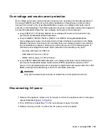
Страница 126: ...way Disconnecting DC power 1 Ensure that the voltage across the DC power source cable leads is 0 V and that the cable leads cannot become active during installation 2 Disconnect the power cable lugs to the negative and the positive DC source power cables Figure 40 or Figure 41 Figure 40 DC power connections to the 4350 chassis h LAO 100306 3magnd1 ...

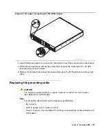
Страница 127: ... cable 5 Remove the screws that connect the power cable lug to the RTN terminal and remove the cable Replacing the grounding cable CAUTION CAUTION The original grounding cable for J series routers is 14 AWG You must replace this cable with a 10 AWG cable Note Note The grounding cable must meet the following specifications Be 10 AWG Able to handle up to 8 Amps of current Have a ring type vinyl insu...

Страница 128: ... cable to the chassis grounding point Figure 42 or Figure 43 Figure 42 Grounding and power connections to the J4350 chassis Figure 43 Grounding and power connections to the J6350 chassis Reconnecting AC power 1 Insert the appliance coupler end of a power cord into the appliance inlet on the power supply faceplate Figure 4 or Figure 5 2 For a J6350 only repeat step 1 for the second power supply 3 I...

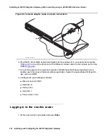
Страница 129: ...ight trip on the cables 6 Restore power to the power leads Turning on the J series router 1 Press the power button to turn on the router Figure 12 The system starts When the system is running normally the Power on LED lights steady green Connecting your PC or laptop to the console port on the J series router 1 Turn off the power to the personal computer or laptop that you use to access the command...

Страница 130: ...erminal emulation application Select the appropriate COM port to use such as COM1 4 Configure the port settings as follows Bits per second 9600 Data bits 8 Parity none Stop bits 1 Flow control none Logging in to the J series router 1 At the login prompt type root and press Enter h LAO 082606 3malapa Ga tew ay AL M AC T TG M5 50 Co ns ole AS B ET R RS T Lin e Tru nk 1 2 3 4 An alo g AL M AC T TI M5...

Страница 131: ...at the router uses to establish a continuous point to point communication session to the TGM550 This session is used for passing control signals and data packets back and forth between the router and the TGM550 and allows an administration access connection from the TGM550 to the router using the session chassis command tgm550_IP_address is the destination IP address used by any other devices over...

Страница 132: ...d non root services access Note Note You cannot use the root login when accessing the router with the session chassis command 1 Obtain an optional login and password from the customer This login is to be used to access the router from the TGM550 with the session chassis command and as a services login to the router 2 At the configure prompt type set system login user user_name class super user whe...

Страница 133: ...ot password change the password to a password agreed upon with the customer administrator Tip Tip After a specific user login and password have been administered on the TGM550 you can alternatively use the following command to log into the TGM550 from the router interface request tgm login fpc slot user tgm user where slot is the slot number of the TGM550 and tgm user is the login of the user Iden...

Страница 134: ...he server review the configuration using the following commands a At the CLI command line type show configuration display set and press Enter b Review the configuration with the project manager or customer to ensure the IP addresses are correct Updating TGM550 firmware if necessary Perform this task if the TGM550 firmware that resides on the TGM550 is not the most recent firmware or is incompatibl...

Страница 135: ...us shows idle For an FTP server type copy ftp SW_image bank filename ftp_server_ip_address to transfer the image from the TFTP server to the TGM550 boot bank where bank is the nonactive boot bank Bank A in the example filename is the full path name of the firmware image file and ftp_server_ip_address is the IP address of the FTP server For example type copy ftp SW_imageA firmware tgm550_26_26_0 bi...

Страница 136: ... TGM550 again The software banner that scrolls on the screen shows the new firmware version 11 If you did no see the firmware version on the software banner then at the TGM550 00 super prompt type show mg list_config The system displays the list of firmware Checking the authentication file ID Avaya personnel only The authentication file is installed at the factory To retrieve the AF ID product ID ...

Страница 137: ...B modem for remote dial in 1 Ensure that ssh service is available on the router Additional services that may be required are FTP and Telnet depending on customer specifications 2 Log in to the router CLI if necessary If you are logged into the TGM550 with ssh from the router then at the TGM550 prompt type exit 3 At the CLI prompt type configure At the configure prompt type set interfaces umd0 dial...

Страница 138: ...revious step and local name is a name for use by host client computers that are outside of the router s domain The dialer uses its assigned access profile to find a CHAP secret for this host The local name can be the same name as the access_profile_name such that remote dial in from other domains can use the same chap secrets of the access profile For example type set interfaces dl1 unit 0 ppp opt...

Страница 139: ...umd0 modem interface For example type set interfaces dl1 unit 0 family inet address 10 6 151 249 30 destination 10 6 151 250 where dialer 1 uses 10 6 151 249 as the incoming IP address from the modem interface and sends 10 6 151 250 as the outgoing IP address set access profile access_profile_name client client_name chap secret chap_secret_string where access_profile_name is the name of the CHAP a...

Страница 140: ...1 PIM WAN DS3 PIM ISDN BRI S T or U PIM ADSL PIM G SHDSL PIM Fast Ethernet PIM and ePIM Serial port Gigabit Ethernet ePIM or uPIM Static route To administer the PIMs see Juniper J2320 J2350 J4350 and J6350 Services Router Getting Started Guide Release 8 4 To administer WAN and security features on the router to support the IG550 voice applications see the following documents as appropriate availab...

Страница 141: ...ware on the S8400 S8500 or S8700 series server please see the Upgrading firmware on programmable TN circuit packs in Upgrading Migrating and Converting Avaya Servers and Gateways 03 300412 1 A third party SSH client must already be installed on your computer PuTTY is one such client available for download from http www putty nl download html A version of PuTTY that is defaulted for SSH server acce...

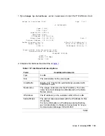
Страница 142: ...erminal type when complete Administering IP interfaces for C LAN circuit packs S8400 S8500 or S8700 series only Note Note This should have already been established as a part of normal S8400 S8500 or S8700 series Server installation change node names ip Page 1 of 1 IP NODE NAMES Name IP Address default_________ 0__ 0__ 0__ 0__ node 1 clan __ 192 168 1 _ 124 node 2 clan 192 168 1 _ 97_ node 10 lsp 1...

Страница 143: ...address on the customer LAN of the C LAN Subnet Mask The subnet mask associated with the IP address for this IP interface For more information on IP addresses and subnetting see Administration for Network Connectivity for Avaya Communication Manager 555 233 504 1 of 2 change ip interfaces 01a03 Page 1 of 1 IP INTERFACES Type C LAN Slot 01A03 Code Suffix TN799 d Node Name procr IP Address 135 9 41 ...

Страница 144: ... is exceeded on an PE interface a procr error is generated Receive Buffer TCP Window Size The threshold for the number of sockets used by this C LAN that triggers a warning message to be sent to the error log Allow H 323 Endpoints Enter a y to allow H 323 endpoint connectivity on this CLAN Enter n if you do not want H 323 endpoints to connect to this CLAN Allow H 248 Gateways Enter y to allow H 24...

Страница 145: ...interfaces field descriptions Field Conditions Comments Type Display only PROCR Node name The unique node name for the IP interface procr is the default node name The node name here must already be administered on the Node Names screen IP Address The IP address on the customer LAN of the Processor Ethernet 1 of 2 change ip interfaces procr Page 1 of 1 IP INTERFACES Type PROCR Node Name procr IP Ad...

Страница 146: ...et Port The Ethernet port must be enabled y before it can be used The port must be disabled n before changes can be made to its attributes on this screen Network Region The region number for this IP interface Target socket load The threshold for the number of sockets used by this interface within the same Gatekeeper Priority as that of other IP interfaces If the targeted number is exceeded on a CL...

Страница 147: ... screen However for the RTCP Enabled and RSVP Enabled fields the entry should be n no 3 Press the Enter key indicated for your terminal type to submit the screen If this is an S8400 S8500 or S8700 series Server and the network region of the TGM550 1 in this example is different from that of media processor board s TN2602AP or TN2302BP in the server s media gateways you must interconnect the two re...

Страница 148: ...sors 6 In this example the media processor is in region 9 and codec set type 3 is to be used for the interconnection between region 1 and region 9 In this example codec type 1 is used for communication within region 1 7 The SAT command list ip codec set lists the types of codecs available on this server 8 For more detail about the Inter Network Region Connection Management form see Administration ...

Страница 149: ...cation Extension field Note Note For more detail about the IP Address Mapping form see Administration for Network Connectivity for Avaya Communication Manager 555 233 504 change ip network map Page 1 of X IP ADDRESS MAPPING Emergency Subnet Location FROM IP Address TO IP Address or Mask Region VLAN Extension 1 __2 __3 __0 1 __2 __3 255 24 __1 ___3 ________ 1 __2 __4 __4 1 __2 __4 __4 32 __2 ___0 _...

Страница 150: ... Tab to the next field The fields on the screen change to reflect the appropriate number of module slots for the router 4 Complete the Name field with the hostname assigned to the router 5 Complete the Serial No field with the serial number of the TGM550 change media gateway 1 Page 1 of 1 MEDIA GATEWAY Number 1 Registered y Type j4350 FW Version HW Vintage 21 13 0 0 Name Swainsons MGP IP Address 1...

Страница 151: ... of the recovery rule if any in the Recovery Rule field The auto fallback recovery rule is set on the system parameters mg recovery rule screen 10 Enter any descriptive information desired in the Site Data field 11 If you are administering the Communication Manager prior to installing the J series router complete the Module Type fields so that the TGM550 and TIMs in each Vx field match the equival...

Страница 152: ...ion and Module Type fields are populated automatically after the TGM550 media gateway registers with the server 15 Type display media gateway gateway_number to view the Media Gateway screen The TIMs installed in the TGM550 are listed next to their slot numbers Verify that a TGM550 media gateway has been successfully added Note Note The slot display in the Media Gateway screen does not match the di...

Страница 153: ...r planning documents at the SAT prompt type enable announcement board gateway_number V9 where gateway_number is the number of the Juniper Service Router you added V9 is the virtual slot for example 2V9 means media gateway number 2 slot V9 Note Note The enable announcement board command fails if you did not complete the V9 field on the Media Gateway screen 2 Press the Enter key indicated for your t...

Страница 154: ...Administering Communication Manager on the server to support the IG550 Integrated Gateway 154 Installing and Configuring the IG550 Integrated Gateway ...

Страница 155: ...r the TGM550 Note Note The sequence of links on the Web site might be different than the sequence in this procedure If you are a customer administrator or an Avaya Business Partner you might be required to access the Download Center Web site to download firmware 1 Go to http www avaya com support 2 Navigate to Downloads The system displays a list of download categories 3 Select Latest TN Circuit P...

Страница 156: ...tarted Guide Release 8 4 Copying the firmware file to a TFTP server or an FTP server 1 To load the firmware on a TGM550 place the firmware file on a TFTP or FTP server that is connected to the customer s LAN A TFTP server is typically a standalone customer computer residing on the customer s LAN or WAN In cases where the supporting Communication Manager server is an S8300 Server that is readily ac...

Страница 157: ...look the same but they are not Do not use the router adapter nor the Ethernet cable to connect to the TGM550 Additionally do not use the TGM550 adapter nor its rollover cable to connect to the router If you use the wrong cable or adapter you may damage the console port As a result it is strongly recommended that you use a permanent marker to label the cables and adapters as soon as you remove them...

Страница 158: ... separately from the router insert them into the router now with the following steps 1 Determine the slots in which to insert the TGM550 TIMs and PIMs The slots must match the configuration you plan to set up on the Communication Manager server In addition the modules must be inserted according to limitations of the supported router models and slots Slot numbering on the routers is as follows J232...

Страница 159: ...S 1 x E3 PIMs are not supported on the J2320 and J2350 routers The 16 port GigaE uPIM 16 Port uPIM requires the space of two vertical slots Therefore the 16 port GigaE uPIM can be inserted into slots as indicated in the following table 2 Ensure power is turned off 3 Attach the blue filter inlet cover see Figure 12 Sample illustration of Juniper Service Router and TGM550 front view J4350 shown on p...

Страница 160: ...slot in the router Then slide the module in until it lodges firmly in the router CAUTION CAUTION Carefully slide the module straight into the slot to avoid damaging the connector components 7 Drive the screws to hold the module in place Figure 45 Inserting the TGM550 and TIMs into the router 8 Retighten the screws on any blank faceplates that you loosened h LAO 100306 3macrdr Analog ALM ACT TIM 51...

Страница 161: ...erminals use one of the following types of combined over voltage and sneak current protection at the building entry point Gas tube with heat coil 4B1E W Solid state with heat coil 4C1S IROB 146C 4 lines or 146F 25 lines Avaya TIM521 ISDN BRI Media Module over voltage and sneak current protection are provided on the Media Modules Network side PSTN applications require an NT 1 device Tie trunk appli...

Страница 162: ...inouts TIM521 A CAT5 cable with an RJ45 connector for one to four BRI trunk connections For each trunk connection insert the CAT5 cable into an NT1 device Then connect the NT1 device to the 2 wire central office connection Juniper PIMs see Juniper J2320 J2350 J4350 and J6350 Services Router Getting Started Guide Release 8 4 2 Insert the cable connector into the port on the interface faceplate 3 Fo...

Страница 163: ...B 9 serial port adapter Figure 46 Note Note Use the specific cable and adapter for the router You cannot use the cable and the adapter that comes with the TGM550 Figure 46 Console adapter cable and port connections h LAO 082606 3malapa Ga tew ay AL M AC T TG M5 50 Co ns ole AS B ET R RS T Lin e Tru nk 1 2 3 4 An alo g AL M AC T TI M5 14 Lin e 5 6 7 8 Lin e 1 2 3 4 E1 T 1 AL M AC T TI M5 10 TS T SI...

Страница 164: ...igure the port settings as follows Bits per second 9600 Data bits 8 Parity none Stop bits 1 Flow control none Logging in to the J series router 1 At the login prompt type root and press Enter 2 At the password prompt enter the password Logging in to the TGM550 1 At the cli prompt type ssh login ip_address where login is root or another valid login if previously administered and ip_address is the I...

Страница 165: ...artition or bank You copy the firmware to this nonactive boot bank 2 At the TGM550 00 super prompt type ping IP_address where IP_address is the address of the TFTP or FTP server 3 Verify that there is a response from the server 4 At the TGM550 00 super prompt type one of the following commands depending on whether the file resides on an FTP server or a TFTP server For a TFTP server type copy tftp ...

Страница 166: ...to complete the file transfer When the transfer is complete the screen will show idle 5 At the TGM550 command line enter show download software status 10 to check the status of the download 6 At the TGM550 command line type set boot bank bank bank where bank is the same letter that you entered in step 2 For example type set boot bank bank A 7 Type copy running config start config CAUTION CAUTION B...

Страница 167: ...rvices Router Getting Started Guide Release 8 4 To administer WAN and security features on the router to support the IG550 voice applications see the following documents as appropriate available at http juniper net J2320 J2350 J4350 and J6350 Services Router Getting Started Guide Release 8 4 J series Services Router Basic LAN and WAN Access Configuration Guide Release 8 4 J series Services Router ...

Страница 168: ...Upgrading an IG550 Integrated Gateway and a Juniper J4350 J6350 Services Router 168 Installing and Configuring the IG550 Integrated Gateway ...

Страница 169: ...al port adapter Figure 47 Note Note Use the specific cable and adapter for the router You cannot use the cable and the adapter that comes with the TGM550 Figure 47 Console adapter cable and port connections h LAO 082606 3malapa Ga tew ay AL M AC T TG M5 50 Co ns ole AS B ET R RS T Lin e Tru nk 1 2 3 4 An alo g AL M AC T TI M5 14 Lin e 5 6 7 8 Lin e 1 2 3 4 E1 T 1 AL M AC T TI M5 10 TS T SI G SO EI...

Страница 170: ...low control none Rebooting the router and changing the root password 1 Press the power button to turn off the router 2 Press the power button again to turn on the router and watch carefully as the system begins to boot up The boot loader displays the boot loading script and briefly stops booting at the following prompt 3 Press the spacebar immediately The ok prompt appears 4 Enter boot s The syste...

Страница 171: ...n appears 11 Enter y The system reboots 12 Log in with the new password when the login prompt appears Recovering the root password of the TGM550 1 Locate an NVRAM INIT jumper The NVRAM INIT jumper is a standard shorting bar jumper A jumper is shipped from the factory in a plastic bag with the TGM550 2 Press and release the power button to turn off the J series router Figure 12 The router begins gr...

Страница 172: ... right behind the console port See Figure 49 h LAO 100306 3macrdr Analog ALM ACT TIM 514 Line 5 6 7 8 Line 1 2 3 4 E1 T 1 ALM ACT TIM 510 TST SIG SO EI SM EM SI EO BRI ALM ACT TIM 521 4 3 2 1 CONSOLE AUX USB 0 1 1 2 3 4 5 6 J4350 POWER POW ER RESET CONFIG STATUS ALARM HA 10 100 100 0 0 0 0 1 0 2 0 3 LIN K TX RX LIN K TX RX LIN K TX RX TX RX LIN K Juniper NETW ORKS Gateway ALM ACT TGM550 Conso le A...

Страница 173: ...RAM pin for storage CAUTION CAUTION Be sure one of the NVRAM pins is free and that both pins are not connected to the jumper If the TGM550 is to be shipped to a different location the jumper should be removed completely from the TGM550 and placed in a bag for shipping Do not lose the NVRAM Init jumper 9 Repeat Steps 5 and 6 You can now log in again with the default root password Note Note Using NV...

Страница 174: ... the Product ID the AF ID and contact services support to retrieve the craft password Restoring the old authentication file on a new TGM550 If you want to remove the authentication file because you have to replace the TGM550 during an installation or upgrade perform the following steps CAUTION CAUTION This procedure should be performed only on a replacement TGM550 not on a new installation of TGM5...

Страница 175: ...he following commands copy auth file tftp filename ip_address copy auth file ftp filename ip_address copy auth file scp filename ip_address where filename is a name you previously gave the authentication file and ip_address is the IP address of the TFTP FTP or SCP server where the file is stored ...

Страница 176: ...Recovering passwords 176 Installing and Configuring the IG550 Integrated Gateway ...

Страница 177: ...p The My Computer window opens 2 Click Help on the My Computer window s toolbar The Help menu opens and displays the version of Windows installed on your laptop 3 Follow one of the two procedures below depending on your operating system Changing TCP IP properties and network settings Windows 2000 and XP 1 Right click My Network Places on your desktop or under the Start menu in XP 2 Select Properti...

Страница 178: ... Click the Advanced button at the bottom of the screen The Advanced TCP IP Settings screen appears c Click the DNS tab Verify that no DNS server is administered The address field should be blank 11 Disable WINS Resolution as follows a Click the WINS tab Make sure WINS is not administered The address field should be blank b Click OK If warned about an empty primary WINS address click Yes to continu...

Страница 179: ...responds to your Ethernet card Windows NT On the Protocols tab select TCP IP in the installed network components list 4 Select the Properties button 5 In the TCP IP Properties box click the IP Address tab 6 Click the radio button to Specify an IP address 7 Enter the following IP address 192 168 1 2 Subnet mask 255 255 255 0 Note Note Record any IP addresses DNS settings or WINS entries that you ch...

Страница 180: ...mation and close the Network dialog box 11 Reboot the system if directed to do so Checking or changing proxy settings Internet Explorer 1 Open your Internet browser 2 Select Tools Internet Options 3 Click the Connections tab 4 Click the LAN Settings button 5 If Use a proxy server for your LAN is not selected no change is necessary click Cancel to exit 6 If Use a proxy server for your LAN is select...

Страница 181: ...twork cable specifications and pinouts TGM550 TIM508 Pin Signal 1 NC 2 NC 3 Ring 4 Tip 5 NC 6 NC Pin Signal Pin Signal Communication Manager port number 1 T 26 R 1 2 T 27 R 2 3 T 28 R 3 4 T 29 R 4 5 T 30 R 5 6 T 31 R 6 7 T 32 R 7 8 T 33 R 8 ...

Страница 182: ...ications and pinouts 182 Installing and Configuring the IG550 Integrated Gateway TIM510 TIM514 Pin Signal 1 R Receive 2 T Receive 3 NC 4 R1 Transmit 5 T1 Transmit 6 NC 7 NC 8 NC Pin Signal 1 NC 2 NC 3 Ring 4 Tip 5 NC 6 NC ...

Страница 183: ... Receive 29 T Send Receive 4 5 T Send Receive 30 T Send Receive 5 6 T Send Receive 31 T Send Receive 6 7 T Send Receive 32 R Send Receive 7 8 T Send Receive 33 R Send Receive 8 17 T Send Receive 42 R Send Receive 9 18 T Send Receive 43 R Send Receive 10 19 T Send Receive 44 R Send Receive 11 20 T Send Receive 45 R Send Receive 12 21 T Send Receive 46 R Send Receive 13 22 T Send Receive 47 R Send R...

Страница 184: ...in Signal Communication Manager port number 1 T Send Receive 26 T Send Receive 1 2 T Send Receive 27 T Send Receive 2 3 T Send Receive 28 T Send Receive 3 4 T Send Receive 29 T Send Receive 4 5 T Send Receive 30 T Send Receive 5 6 T Send Receive 31 T Send Receive 6 7 T Send Receive 32 R Send Receive 7 8 T Send Receive 33 R Send Receive 8 17 T Send Receive 42 R Send Receive 9 18 T Send Receive 43 R...

Страница 185: ...e 46 R Send Receive 13 22 T Send Receive 47 R Send Receive 14 23 T Send Receive 48 R Send Receive 15 24 T Send Receive 49 R Send Receive 16 Pin Signal Pin Signal Communication Manager port number Pin Signal 1 NC 2 NC 3 Transmit pair 4 Receive pair 5 Receive pair 6 Transmit pair 7 NC 8 NC ...

Страница 186: ...uniper console port connector pinouts TGM550 RJ 45 Pin Name DCE View Terminal DB 9 Pins 1 For future use NC 2 TXD TGM550input 3 3 RXD TGM550 output 2 4 CD 4 5 GND 5 6 DTR 1 7 RTS 8 8 CTS 7 Pin Signal Description 1 Unused 2 DSR Data Set Ready 3 RD Receive Data 4 GND Signal Ground 5 GND Signal Ground 6 TD Transmit Data 7 DTR Data Terminal Ready 8 Unused ...

Страница 187: ... make the equipment unsafe Never attempt to lift an object that is too heavy for one person to handle Never install or manipulate wiring during electrical storms Never install electrical jacks in wet locations unless the jacks are specifically designed for wet environments Operate the router only when it is properly grounded The separate protective earthing terminal provided on this product shall ...

Страница 188: ...ic discharge ESD damage which can cause intermittent or complete component failures Always use an ESD wrist strap or ankle strap and make sure that it is in direct contact with your skin DANGER DANGER For safety periodically check the resistance value of the ESD strap The measurement should be in the range of 1 to 10 Mohms When handling any component that is removed from the chassis make sure the ...

Страница 189: ...dering a VoIP module quote the following comcode Replacing a VoIP module The TGM550 has one slot for a VoIP module The slot can accommodate either an MP80 MP20 or an MP10 VoIP module providing 80 20 or 10 VoIP channels respectively Replacing the VoIP module requires the following steps 1 Removing the TGM550 module 2 Removing a VoIP module 3 Inserting a VoIP module 4 Reinserting the TGM550 module T...

Страница 190: ... or removing the Avaya TGM550 module This module is not hot swappable If you attempt to remove or insert the module while the router is turned on the router might reset or malfunction in some other way 2 Using a small Phillips screw driver remove the screws holding the TGM550 module in place see Figure 50 Figure 50 Removing and inserting the TGM550 module 3 Remove the TGM550 module from the router...

Страница 191: ...module lifts up 3 Pull out the VoIP module Touch the module only at the edges Inserting a VoIP module 1 Position the VoIP module at a 45 degree angle to the TGM550 module and start inserting it into its slot see Figure 51 Figure 51 Inserting the VoIP module 2 Push the VoIP module in all the way Do not use too much force 3 Flatten the VoIP module so it is flush with the TGM550 module The latches at...

Страница 192: ...riginal slot Align the notches in the connector at the rear of the TGM550 with the notches in the slot in the router Then slide the module in until it lodges firmly in the router CAUTION CAUTION Carefully slide the module straight into the slot to avoid damaging the connector components 2 Drive the screws to hold the TGM550 module in place see Figure 50 3 Power on the router ...

Страница 193: ...ttings 33 75 103 130 164 170 TGM550 186 controller list 106 configuring 72 copy ftp SW_image command 38 78 109 135 166 copy running config start config command38 79 110 135 166 craft authentication file 39 79 111 136 customer options administering 153 D DC power connecting to chassis 26 59 99 129 disconnecting to chassis 126 default gateway 65 Disk on Key configuration data 43 inserting 29 DNS ser...

Страница 194: ... 35 telephony upgrade 117 155 upgrading software 13 49 89 118 156 JUNOS software compatibility 12 45 85 117 JUNOS software upgrading 13 49 89 118 156 J Web configuration 64 connecting laptop 62 J Web interface accessing 64 laptop settings 177 L laptop connecting to router 62 connecting to router console port33 74 102 129 163 169 LEDs J series router 29 102 logging in Communication Manager 141 J se...

Страница 195: ...d 39 79 110 136 167 show recovery command 36 76 108 show system command 36 133 software compatibility 12 45 85 117 upgrading router 13 49 89 118 156 SSH enabling 65 T T1 interface configuring 73 107 T3 interface configuring 73 107 TCP IP settings laptop Ethernet connection 177 179 telephony upgrade 117 155 Telnet enabling 65 enabling on router 35 TGM550 adding as a media gateway 150 cabling 22 55 ...

Страница 196: ...196 Installing and Configuring the IG550 Integrated Gateway Index ...

Отзывы: