


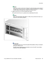


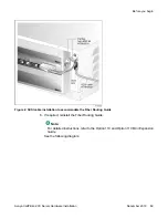


The SCSI device connector end is equipped with a bracket assembly. This bracket assembly
attaches to the Option 11C below the card cage. The CD-ROM or tape drive connects to this
bracket assembly with the NTRH3502 cable that is provided with the device.
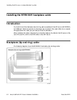
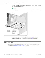
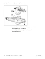
What the completed installation looks like
The following diagram shows how the intermediate SCSI cable, CD-ROM drive, and tape drive
are connected to the Option 11C. The CD-ROM drive is the first device. The tape drive is the
last device.
What the completed installation looks like
Avaya CallPilot
®
201i Server Hardware Installation
December 2010 61
Содержание CallPilot 201i
Страница 1: ...Avaya CallPilot 201i Server Hardware Installation 5 0 NN44200 301 01 03 December 2010 ...
Страница 8: ...8 Avaya CallPilot 201i Server Hardware Installation December 2010 ...
Страница 28: ...About the 201i server 28 Avaya CallPilot 201i Server Hardware Installation December 2010 ...
Страница 106: ...Preparing peripheral devices 106 Avaya CallPilot 201i Server Hardware Installation December 2010 ...
Страница 128: ...Connecting peripheral devices to the 201i server 128 Avaya CallPilot 201i Server Hardware Installation December 2010 ...