


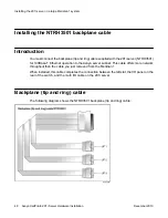


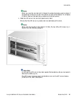


Note:
The backplane connectors for the right slot are not required and, therefore, are
left vacant.
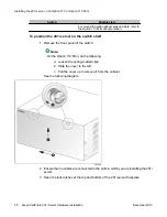
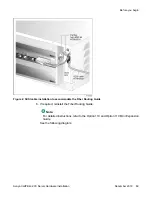
6. Thread the NTRH1410 cable through the shelves below and out through the bottom
of the Meridian 1 tower.
7. Replace the protective plate.
8. Replace the I/O panel cover.
9. Power up the shelf.
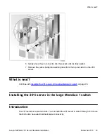
What is next?
Prepare the modem, CD-ROM drive, and tape drive for connection to the 201i server. For
instructions, see
What is next?
Avaya CallPilot
®
201i Server Hardware Installation
December 2010 55
Содержание CallPilot 201i
Страница 1: ...Avaya CallPilot 201i Server Hardware Installation 5 0 NN44200 301 01 03 December 2010 ...
Страница 8: ...8 Avaya CallPilot 201i Server Hardware Installation December 2010 ...
Страница 28: ...About the 201i server 28 Avaya CallPilot 201i Server Hardware Installation December 2010 ...
Страница 106: ...Preparing peripheral devices 106 Avaya CallPilot 201i Server Hardware Installation December 2010 ...
Страница 128: ...Connecting peripheral devices to the 201i server 128 Avaya CallPilot 201i Server Hardware Installation December 2010 ...