


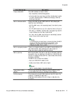


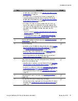


Connector type
Purpose
• user desktop computers, to enable use of the unified
messaging and fax messaging features
• LAN-based server administration
Important:
If you need Ethernet 100Base-T operation at 100 Mbit/s on
large Meridian 1 systems (such as Option 51), you must install
the NTRH3501 backplane (tip and ring) cable. For more
information, see
Installing the 201i server in a large Meridian
on page 37.
RS-232 COM1 (male
DB-9)
This connector provides the connection to an external modem.
The modem allows administrators and technical support
personnel to administer the 201i server from a remote location.
Peripheral connectivity
Introduction
Peripheral equipment is attached to the 201i server on the server faceplate.
Faceplate connections
Important:
Connections made to the faceplate (with the exceptions noted below) are temporary only,
because you must remove the cabinet cover to make these connections. The system does
not meet specifications for radiated EMI if you remove the cabinet cover.
The following peripheral devices connect to the 201i server faceplate:
• monitor (SVGA)
• keyboard
• mouse
• MPC card (permanent connection)
• SCSI cable (permanent connection)
About the 201i server
24 Avaya CallPilot
®
201i Server Hardware Installation
December 2010
Содержание CallPilot 201i
Страница 1: ...Avaya CallPilot 201i Server Hardware Installation 5 0 NN44200 301 01 03 December 2010 ...
Страница 8: ...8 Avaya CallPilot 201i Server Hardware Installation December 2010 ...
Страница 28: ...About the 201i server 28 Avaya CallPilot 201i Server Hardware Installation December 2010 ...
Страница 106: ...Preparing peripheral devices 106 Avaya CallPilot 201i Server Hardware Installation December 2010 ...
Страница 128: ...Connecting peripheral devices to the 201i server 128 Avaya CallPilot 201i Server Hardware Installation December 2010 ...