

a. Prepare the rack
• Provide the equivalent of two racks of vertical space for each 59100 in
an EIA or IEC-standard 19-inch (48.2-centimeter) equipment rack.
• Ensure that the equipment rack is stable and securely attached to a
permanent structure.
• Ground the rack to the same grounding electrode used by the power
service in the area. The ground path must be permanent and must not
exceed 1 Ohm of resistance from the rack to the grounding electrode.
AVAYA recommends using a filter or surge suppressor.
b. When you install the switch into a network, ensure to use the
following cables:
• Category 5E or higher specification cabling must be used for 1
Gbps/1000 Mbps operation.
• RJ-45 and DB-9 console port cables and adaptors are as follows:
Confirm that you have the tools and package contents as follows:
Tools Required:
• Phillips #2 screwdriver
• Console cable to match the console connector on the switch (DB-9 or RJ-45)
• ESD cable (optional)
Package Contents:
Ethernet Routing Switch
59100 Series
Quick Install Guide
Avaya
1.
Avaya Ethernet Routing Switch 59100 Series.
2.
Rack-mounting hardware that includes:
a. Rack-mount brackets
b. Screws to attach brackets to the switch
3.
AC power cord.
(Note: A power cord is not included for the A variant of the switch)
4.
Documentation includes the Quick Install poster and
Regulatory document.
5.
One field replaceable power supply unit.
Note:
Four field replaceable power supplies are supported for models
ERS 59100GTS and ERS 59100GTS-PWR+.
6.
Four fan tray modules.
Note:
Items 5 and 6 do not come with the switch.
These items come in separate package.
1
Before you start
For detailed information about installing the Ethernet Routing Switch 5900
Series switches, see Installing Avaya ERS 5900 Series (NN47211-300).
All documents referenced in this Quick Installation Guide can be
downloaded at www.avaya.com.
Depending on your hardware model, your switch may appear different than
the figures shown in this guide.
Note:
Be sure to order Direct Attach cables and SFP or SFP+ Transceivers
if required.
For...
Order
Order Code
Front-to-Back
cooling
AC Power Supply Front2Back
Cooling (no Power Cord*)
AL7000A0F-E6
AL1905A3F-E6
Quantity
1 to 4**
Back-to-Front
cooling
AC Power Supply Back2Front
Cooling (no Power Cord*)
AL7000A0B-E6
AL1905A3B-E6
1 to 4**
4-post rack
mount bracket
(sold separately)
Four Post Server Rack Mount Kit
(optional) for ERS 59100GTS and
ERS59100GTS-PWR+
AL5911001-E6
1
Console cabling
(sold separately)
Avaya RJ-45/DB-9 Integrated
console cable
Note:
1.8m cable with DB-9
Female for PC and RJ-45 for
device console port
AL2011022-E6
1
Be sure to order Direct Attach cables and SFP or SFP+ Transceivers as required. See
Installing Transceivers and Optical Components on Avaya Ethernet Switch 5900 Series
(NN47211-302) for more information.
*
F2B power supply and power cord variants: (non-PWR+)
AL7000B0F-E6 = Europe, AL7000C0F-E6 = UK,
AL7000D0F-E6 = Japan, AL7000E0F-E6 = North America,
AL7000F0F-E6 = Australia/New Zealand
B2F power supply and power cord variants (non-PWR+)
AL7000B0B-E6 = Europe, AL7000C0B-E6 = UK,
AL7000D0B-E6 = Japan, AL7000E0B-E6 = North America,
AL7000F0B-E6 = Australia/New Zealand
*
F2B power supply and power cord variants (PWR+):
AL1905B3F-E6 = Europe, AL1905C3F-E6 = UK,
AL1905D4F-E6 = Japan, AL1905E4F-E6 = North America,
AL1905F4F-E6 = Australia/New Zealand
B2F power supply and power cord variants (PWR+)
AL1905B3B-E6 = Europe, AL1905C3B-E6 = UK,
AL1905D4B-E6 = Japan, AL1905E4B-E6 = North America,
AL1905F4B-E6 = Australia/New Zealand
** Avaya recommends four power supplies for redundancy, load
sharing and full hot-swap replacement of a power supply for uninterruptible operation
Chassis without
fans or PSUs
Chassis without PSU, fans, and
power cord
AL590005X-E6
and AL590006X-E6
1
• Unpack the Avaya Ethernet Routing Switch 59100.
• Observe ESD precautions when unpacking.
• The switch ships with a filler panel in the second power supply position. This filler
panel must stay in place if you do not intend to install a second power supply.
2
Unpack equipment
1.
Attach a bracket to each
side of the switch.
Install using the optional 4-post rack mount bracket
1.
Attach the two sets of front brackets to each guide bracket using sixteen
8.5 mm length flat head machine screws.
2.
Attach the guide brackets to the switch chassis.
a.
Use four M4 x 5.5 mm low profile undercut flat-head hex machine
screws to attach the rear of each guide bracket to the chassis.
b.
Verify if rear screws sit flush in the guide brackets.
c.
Test fit the rear mounting brackets in the guide brackets and verify that
the rear brackets can slide in the channels. Remove the rear brackets.
3.
Install the switch into the equipment rack temporarily using only the front
rack mounts and screws.
4.
Slide a rear mounting bracket into each
guide bracket channel until flush
with the rear rack posts.
a. Slide a rear mounting bracket
into each guide bracket
channel until flush with
the rear rack posts.
b. Secure the rear
mounting brackets
to the switch chassis
with the pan-head screws.
3
PEC Code Name
Short Description
AL2011022-E6 Avaya RJ-45/DB-9
CONSOLE CABLE
1.8m cable with DB-9 Female for terminal/PC
on one end and RJ-45 for device console
port connectivity on the other.
PEC Code
Description
AA1404037-E6
QSFP+ to QSFP+ 40G 0.5 m (Passive)
AA1404029-E6
QSFP+ to QSFP+ 40G 1 m (Passive)
AA1404031-E6
QSFP+ to QSFP+ 40G 3 m (Passive)
AA1404032-E6
QSFP+ to QSFP+ 40G 5 m (Passive)
c. Stacking cables:
4
Rack mounting
2.
Slide the switch into the
rack. Insert and tighten
the rack-mount screws.
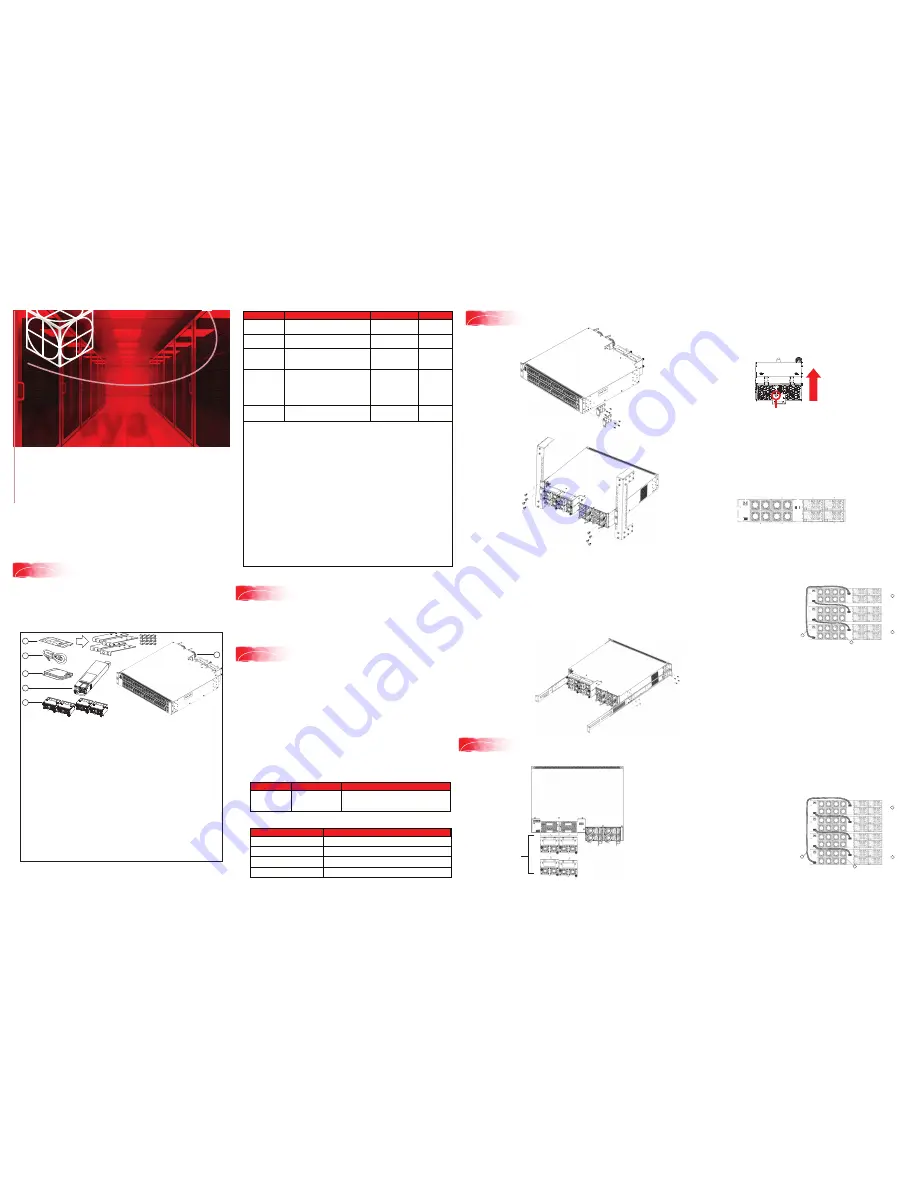
For correct switch operation, install both Fan Trays so that the airflow direction
matches the primary Power Supply.
Fan trays can only be inserted in one direction.
• Use the location pin on the Fan Tray to ensure correct orientation in the
chassis. The Fan Tray is upright if the location pin is at the top.
• Once the Fan Tray is installed, tighten the thumbscrews.
Stacking
The Avaya Ethernet Routing Switch 59100 Series provides fail-safe stackability.
You can connect up to four 59100 Series devices in a stack to provide
uninterrupted connectivity for up to 384 ports. You can manage the stack as a
single unit.
The Avaya Ethernet Routing Switch 59100 series back panel provides a Base
Unit switch, Cascade Down connector, and Cascade Up connector for stacking
purposes as shown below:
SDN/Aux Port
Cascade
Down Port
Cascade Up Port
Base Select
Switch
Base Unit Switch
– used to designate the base unit in a stack. When set to the
DOWN position, this unit acts as the Base Unit for the stack.
Cascade Down and Cascade Up connectors
– used to connect a switch to the
next unit in the stack through a cascade cable. Connect one end of the Cascade
Down cable to the Cascade Up connector of the next switch in the stack (shown
in the simple three-switch stack connection block diagram below):
Simplified Stacking diagram
1 = Base unit
2 = Last unit
3 = 0.5m Cascade/Stack cable
4 = 1.0m Cascade/Stack cable
To create a stack connection, order the appropriate Avaya Ethernet Routing
Switch 59100 Series cascade cables to ensure fail-safe stacking. For stacking
three or more units (maximum stack port count cannot exceed 416 ports, or
4 units), order 0.5 m, 1 m, 3 m or 5 m cables as applicable.
1.
Ensure that all switches for the stack are rack mounted.
2.
Slide the Unit Select switches on the back of the units to the appropriate
position, depending on whether they are a base unit or non-base unit:
•
Base Unit (Unit 1)
- Slide the Base Unit switch to the DOWN position.
•
Non-Base Unit (Units 2-4)
- Slide the Unit Select switch to the UP position.
Because stack parameters are associated with the base unit, the physical
stack order depends on the base unit position and whether you configure
the stack cascade up (stack up) or cascade down (stack down). This
designation depends on the stack cabling arrangement.
NOTE:
Avaya recommends you use a Cascade Down (stack down)
configuration.
3.
For a Cascade Down configuration, connect stack cables as shown below:
Cascade Down configuration
1 = Base unit
2 = Last unit
3 = 0.5m Cascade/Stack cable
4 = 1.0m Cascade/Stack cable
(Return cable)
Note:
Return cable length may
vary depending on unit spacing.
Please ensure proper length
return cable is ordered to
provide adequate strain relief.
Fan Tray
Location pin
Upright
5
Install four Fan Trays in the ERS 59100 switch
Fan Trays
1
2
3
4
Unit 1
Unit 2
Unit 3
5
4
3
2
1
6
1
Unit 4
Unit 1
Unit 2
Unit 3
2
3
4