JNX30D TECHNICAL REFERENCE MANUAL
VERSION: 1.4
Page 14 of 28
FEB 2022
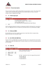
5.13
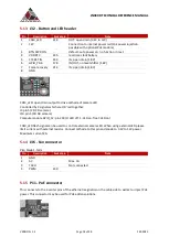
J32 - Button and LED header
Pin
Description
Socket pin
Note
1
CAM_LED
218
OUT: open drain (3.3V to 12V)
2
12V
Connection to internal power rail (PoE power injection
possible with optional PoE module)
3
BTN PWR ON
-
default: auto power on, no function in rev 1
4
VDD RTC
235
real time clock battery
5
SYS RST IN
239
IN, open drain (1.8V)
6
GPIO_PA6
178
IN/OUT, no level shifter (1.8V)
7
Force recovery
214
IN: open drain (1.8V)
8
GND
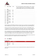
CAM_LED: open drain output to drive cathode of camera LED.
Controlled by 3 signals which are OR ‘red together:
J5 pin 5 (CSI CD camera)
J10 pin 5 (CSI AB camera)
Compute module GPIO_12: pin 218 (0: LED off, 1: LED on, float: LED on)
CAM_LED flash signal can be used to control external camera LED. When using external LED please
limit current with external resistor. Connect cathode to this pin and anode to 3.3V to 12V power.
Maximum current 2A.
5.14
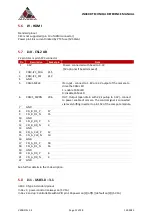
J36 - Fan connector
Pico blade 1.5mm
Pin
Description
Socket pin
Note
1
GND
2
5V
Max. 1A
3
TACH
-
Not connected
4
PWM
230
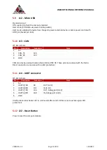
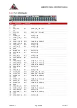
5.15
P11 - PoE connector
This connects to the 4 center pins of the ethernet magnetics on the cable side to extract or inject PoE
power. This connector may be used for PoE addon solutions.


