JNX30D TECHNICAL REFERENCE MANUAL
VERSION: 1.4
Page 11 of 28
FEB 2022
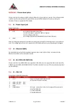
6
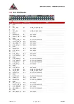
CAM2_PWDN
206
OUT: Output (open drain with 2.2k pullup to 3.3V) - connect
to power enable of camera. The control signal is connected
via level shifting inverter to pin 152 of the compute module.
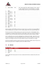
7
GND
8
CSI_D_D1_P
66
9
CSI_D_D1_N
64
10 GND
11 CSI_D_D0_P
42
12 CSI_D_D0_N
40
13 GND
14 CSI_C_CLK_P
54
15 CSI_C_CLK_N
52
16 GND
17 CSI_C_D1_P
60
18 CSI_C_D1_N
58
19 GND
20 CSI_C_D0_P
48
21 CSI_C_D0_N
46
22 GND
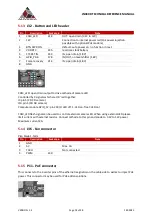
Please note that on the JNX30D each camera connector uses its own I2C bus. This setup is different
from the NVIDIA dev kit. If you like to use CSI-2 cameras, please install the Auvidea BSP (firmware).
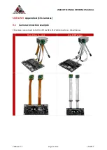
This CSI-2 connector has the same 22 pin pinout as the 22 pin connector on the Raspberry Pi Zero
and Raspberry Pi compute module dev kit board. With adapter cable it may connect to Raspberry Pi
camera 2.1 and Vision Component camera modules. Alvium cameras require the Alivium adapter.
Pin 6: by default the device tree puts a PWM signal on pin 206 (LCD_BL_PWM - GPIO_07). For most
cameras (like Raspberry Pi camera with iMX219 sensor) this needs to be changed to a constant low
output to send a high to the camera for power enable. This is part of the device tree changes.
Some Vision Component camera modules use this pin to synchronise multiple cameras. The pin 5s of
all CSI-2 connectors are OR ‘red together and drive the CAM LED output.
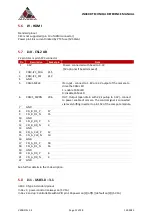
5.5
J8 - USB 2.0
JST-GH 1.25mm
Pin
Description
Socket pin
Note
1
5V
2
USB2_D_N
121
3
USB2_D_P
123
4
GND
Internal USB 2.0 JST-GH connector to connect to internal USB 2.0 add-on modules (like U100, U110,
U120, etc).


