background image

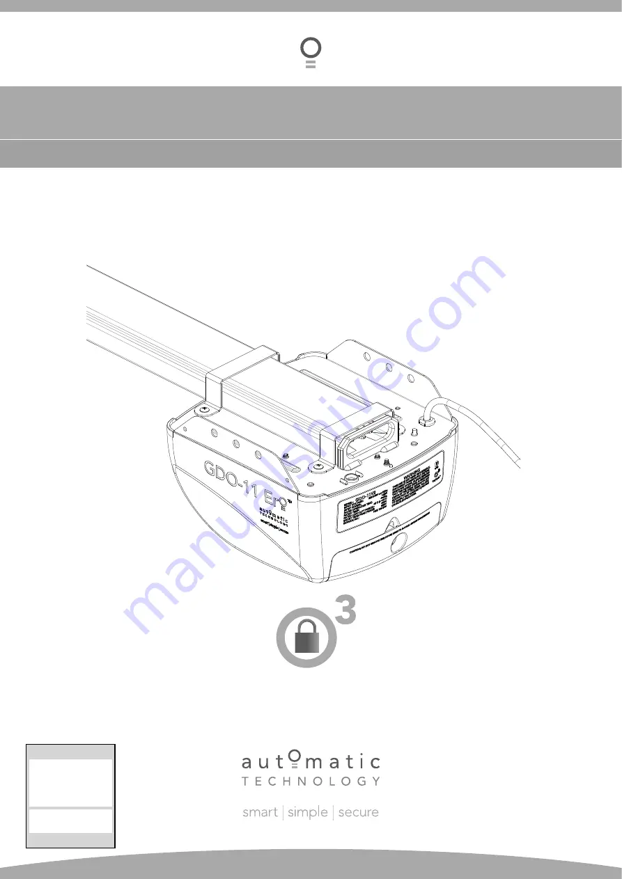
GDO-11v2 Ero™

Overhead Garage Door Opener

Featuring

TrioCode

Technology


Technical Document

Installation Manual

v

1.00

21 Feb 2012

English

Part # 13239 (Manual)

Содержание GDO-11 Ero

Страница 1: ...GDO 11v2 Ero Overhead Garage Door Opener Featuring TrioCode Technology Technical Document Installation Manual v1 00 21 Feb 2012 English Part 13239 Manual ...

Страница 2: ...wfully excluded hereby expressly disclaims all conditions or warranties statutory or otherwise which may be implied by laws as conditions or warranties of purchase of an Automatic Technology Australia Pty Ltd Overhead Door Opener Automatic Technology Australia Pty Ltd hereby further expressly excludes all or any liability for any injury damage cost expense or claim whatsoever suffered by any perso...

Страница 3: ... 19 Safety Obstruction Forces 20 Safety Obstruction Force Test 20 Adjusting Safety Obstruction Forces 21 Coding Transmitters 22 Door 22 Vacation Mode 22 Auxiliary Out Put 22 Pet Mode 23 Courtesy Light 23 Remotely Coding Transmitters 24 Erasing Transmitter Codes 24 Accessories 25 Safety Beam Installation 25 Auxiliary output Key switch 26 Battery Backup installation 26 SmartSolar Installation 28 Fin...

Страница 4: ...ow this warning Regularly check to make sure that the Safety Obstruction Force is working correctly and is tested and set as per page 20 of this manual Failure to follow these instructions could result in serious personal injury and or property damage This test must be repeated at regular intervals and the necessary adjustments made as required A Safety Beam must be used if the closing force as me...

Страница 5: ...ener Connect the opener to a properly earthed general purpose 240V mains power outlet installed by a qualified electrical contractor Disconnect the power cord from mains power before making any repairs or removing covers Only experienced service personnel should remove covers from the opener In order for the Ero to sense an object obstructing the door way some force must be exerted on the object As...

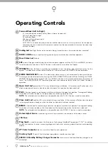
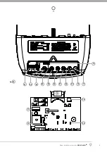
Страница 6: ...rts such as cams and microswitches During installation the handheld transmitter can be programmed to set the limits positions ISS Intelligent Safety Obstruction System While the door is performing a close cycle should it hit an obstacle or be restricted in some manner it will automatically reverse The amount of force the door should encounter before reversing is automatically adjusted by the doors...

Страница 7: ...sed when the door is left idle for long periods of time Pet Pedestrian mode The transmitter can be programmed to open the door to an adjustable partial height so that the family pet can enter and exit the garage at any time You may also wish to open the door to a height suitable only for pedestrian access Safety Beam optional The opener has an input to connect a Safety Beam for extra safety Manual...

Страница 8: ...hould only be used if environmental factors wind etc affect the door s operation Open Limit Led green the LED is very helpful during installation It illuminates and flashes when the door is opening and remains steady on when the open limit position has been reached PLUS button green is used during installation to help set the open limit position Pressing and holding this button will move the door i...

Страница 9: ...Owner Installation Instructions GDO 11v2 Ero 9 12 01 02 03 04 05 06 07 08 09 10 11 01 fig 13 16 14 15 17 ...

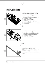
Страница 10: ...eves and four C rail tracks 1 x Shuttle assembly Fig 2 1 x Installation Manual Power Head And Accessory pack 1 x GDO 11v2 Ero drive unit Fig 3 1 x TrioCode Transmitter pack Fig 3 Pack includes 1x four button keyring transmitter and 1x two button keyring transmitter with batteries 2 x Door attachment arms Fig 3 1 x Accessory and hardware pack Fig 3 1 x Installation Manual Pre Assembled Single Piece...

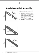
Страница 11: ...d lay chain out on floor do not allow chain to twist Loop the chain onto the pulley of tension chain assembly Slide the tension chain assembly with chain into the track Fig 06 Slide shuttle assembly into opener end the track assembly Be sure to insert shuttle assembly with hole side toward the door as shown with arrow in Fig 07 Push the sprocket support into opener end of the track Feed the chain t...

Страница 12: ...nto the sprocket and also wrapped around the centre of the pulley i Use a spring scale to measure required force to pull the shuttle adjust 1 2 tension hex bolt Fig 09 to tension the chain j Move the shuttle back to the centre of the track to re test the force with spring scale Fig 10 k Continue to adjust the tension hex bolt until a force of 8kg to 8 5 Kg is achieved Door end Opener end Door end ...

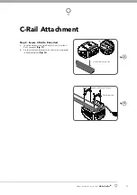
Страница 13: ...Locate shaft into sprocket Shaft Mushroom Head Screw Taptite S M4 x 8 Track bracket x2 Step 2 Secure C Rail to Drive Unit Locate and insert the shaft of drive unit into the C Rail s sprocket Fig 11 Fix the two track brackets with four screws supplied in accessory pack Fig 12 a b ...

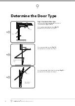
Страница 14: ...5 For a sectional panel door on tracks Fig 13 proceed with the installation from Step 4 For a one piece door on tracks Fig 14 proceed with the installation from Step 4 For a one piece door without tracks on springs Fig 15 proceed with the installation from Step 8 13 fig 14 fig 15 fig Door Sectional door with track Door Track One piece door with track One piece door without track ...

Страница 15: ...r lintels are solid and sound so as to form a secure mounting platform Step 6 Attach The C Rail To The Wall Bracket Attach the C Rail assembly to the wall bracket with the 90mm long clevis pin and secure with the supplied snap pin Fig 18 Leave the drive unit in its packing box for protection during installation Step 7 Secure The Drive Unit To The Ceiling Raise the drive unit from the packing box a...

Страница 16: ...line determined in Step 8 Using the bracket as a template mark a minimum of two holes and drill with appropriate size bit For a more secure fitting the wall bracket can be anchored using more than two holes Secure the bracket to the wall using IF CONCRETE OR BRICK 8mm 5 6 loxins dynabolts IF TIMBER wood screw 20 or similar min 50mm Attach the bracket and C Rail with supplied pins Fig 18 WARNING Mak...

Страница 17: ... Track Assemble the bent arm connecting to the door to the right side of the straight arm connecting to the shuttle with bolts and nuts supplied in the accessory pack Fig 25 Always use both bent and straight arms Connect the assembled arm to the bracket and the disengaged trolley with clevis and snap pins The angle A must be more than 10 Fig 26 WARNING Connecting the bent arm the other way around ...

Страница 18: ...is halfway up turn the DATUM ADJUST screw until the light goes off then turn back one notch to illuminate again Step 14 4 Set the Limits Positions Press and hold the MINUS button until the door reaches the desired close limit position Single presses will inch the door closed Fig 30 Press the LIMIT SET button to store the close position into memory Fig 30 Press and hold the PLUS button until the do...

Страница 19: ...too far press Button 1 to inch the door towards open When happy with the close limit position press Button 2 to store this in memory Press Button 1 to open the door When approx 2 cm from the desired open position release button 1 A brief press of Button 1 will allow you to inch the door open Keep doing this until the door reaches the desired open limit position If the door is opened too far press ...

Страница 20: ...am must be installed if the closing force at the bottom edge of the door exceeds 400N 40kg force Step 16 1 Testing Close Cycle Press the OPERATE button to open the door Fig 33 Place a piece of timber approximately 40mm high on the floor directly under the door Fig 34 Press the OPERATE button to close door The door should strike the object and start to re open Step 16 2 Testing Open Cycle Press the ...

Страница 21: ...n FORCE MARGIN SET button Fig 35 While holding the FORCE MARGIN SET button press the MINUS button Each press decreases the force margin Fig 35 The CLOSE LIMIT LED will flash each time the MINUS button is pressed to indicate a force decrease If the CLOSE LIMIT LED is on continuously when pressing the MINUS button this indicates that the minimum setting has been reached Test the force again as per St...

Страница 22: ...d will beep two times on second press Fig 39 Press one of the four 4 buttons on the transmitter for two 2 seconds pause for two 2 seconds then press the same button again for two 2 seconds Release DOOR CODE button Press and hold the transmitter button for six 6 seconds to set Vacation Mode The door code LED will stay lit while Vacation Mode is active To reset Vacation Mode press the same button fo...

Страница 23: ...itter button to test To change the default pet pedestrian door opening position refer Step 25 Step 18 5 Coding a Transmitter Button to the Courtesy Light The transmitter can be programmed to operate the courtesy light on the opener independently of the door moving Briefly press the DOOR CODE button four times then press it again and hold will beep five times on fifth press Fig 42 Press one of the fou...

Страница 24: ...onds and then release Wait for 10 seconds and then press the new transmitter s button to test Step 19 1 Deleting a Stored Transmitter Code Select the transmitter you want to delete Press and hold the DOOR CODE BUTTON Fig 44 Press the transmitter button you would like to delete for two seconds pause for two seconds press again for two seconds and then release Release the DOOR CODE BUTTON The code s...

Страница 25: ...0mm above the floor level and as close as possible to the door opening Connect as per the wiring diagram Fig 48 Step 20 2 Alignment Power up the GDO11V2 with the Safety Beam connected The green LED on the transmitter should turn ON to indicate power is present If the receiver is connected to power and the red LED is flashing while the green LED on the transmitter is on the transmitter and receiver a...

Страница 26: ...o 9 to j4 connector Feed the SBY 2 battery harness item no 10 through the grommet on the metal plate and connect to the terminal marked battery on the SBC02 as shown in wiring diagram refit the main cover with screws marked S in Fig 51 Secure the Battery Backup to GDO 11v2 Ero with 2 hex standoff M4 item no 11 and 4 screws item no 13 WARNING After Step 22 1 f the opener may become active even when ...

Страница 27: ...Owner Installation Instructions GDO 11v2 Ero 27 Accessories 52 fig ...

Страница 28: ...e Solar Panel s cable through black grommet located on the top of the metal plate Connect the red wire to the Charger Board s SOLAR connector and the black wire to the SOLAR connector Fig 52 WARNING During Step 24 3 the opener will become active Step 23 3 Mount Connect the Battery Mount the Battery Box close to the opener Feed the 2 core 18awg gauge cable supplied through the Battery Box s grommet...

Страница 29: ...illuminated If a Pet Mode button is pressed while the door is moving the door will stop If a Pet Mode button is pressed when the door is in the Pet position then the door will close Step 25 Installing the Wall Mounted Transmitter Optional Remove the faceplate from the transmitter Affix the baseplate in a convenient wall location Fig 58 that is out of reach of children at a height of at least 1 5 me...

Страница 30: ...m 100 kg Minimum Clearance Bottom of C Rail to highest point of door travel 40mm Short term peak force 650N 65kg Lift force 400N 40kg Nominal force 150N 15kg Receiver type Multi frequency FM Receiver Receiver code storage capacity 8 x 4 button transmitter codes Transmitter frequency 433 47 433 92 434 37 MHz Coding type TrioCode Number of code combinations Over 4 29 billion random codes Code genera...

Страница 31: ...on Auxilary function Pet mode and Light function FORCE MARGIN SET OPEN Increases the obstruction force margin setting FORCE MARGIN SET CLOSE Decreases the obstruction force margin setting FORCE MARGIN SET then SET Resets the factory default force margin settings CLOSE for 6 secs Clears the door limits set positions Limits then need to be reset PLUS for 6 secs Enters pet pedestrian position mode SE...

Страница 32: ...e battery Door will not close fully Door limits position need to be reset Reset limits positions Refer Step 15 4 on page 19 Door will not open fully Door limits position need to be reset Reset limits positions Refer Step 15 4 on page 19 Courtesy light not working Faulty light Replace lamp Door does not reverse open when Safety Beam is obstructed during close cycle Safety Beam not aligned correctly...

Страница 33: ...he door contacts a 40mm high object placed on the floor AS3350 NOTE If the door does not operate smoothly call your door professional Yearly Automatic Technology suggests you contact your door professional to perform an annual door service CAUTION Frequently examine door particularly cables springs and mountings for signs of wear damage or imbalance Do not use if repair or adjustment is needed sinc...

Страница 34: ...34 GDO 11v2 Ero Owner Installation Instructions Parts Listing 60 fig ...

Страница 35: ... use of the Product contrary to the instructions supplied with the Product g maximum continuous operating time exceeding 1 minute in 10 h the operating force exceeding 15kg 150 Newton when moving the door manually to the open or closed position i the door surface area exceeding 13 5m2 j the door used with the Product not being in safe working order and condition k repairs which are not authorised ...

Страница 36: ... Pty Ltd No part of this document may be reproduced without prior permission In an ongoing commitment to product quality we reserve the right to change specification without notice E OE Automatic Technololgy Australia Pty Ltd ABN 11 007 125 368 6 8 Fiveways Boulevard Keysborough Victoria 3173 Australia P 1300 133 944 61 2 9722 5666 International Enquiries Only E sales ata aust com au www ata aust c...

Отзывы: