The informat ion conta ined in th is docu ment is the property of Automatic Syst ems and is conf ident ial . The recip ient shall refr ain from us ing it for any purpose
other than the use of the produ cts or t he e xecut ion of the projec t to wh ich it refers and from commun icat ing it to th ird parties w ithout wr itten pr ior agree m ent
of Automat ic Systems.
RSB76E-MT-EN
p. 11/33
3.5. Electrical
Connections
WARNING
: do not connect to a floating network or to high impedance earthed industrial
distribution network.
WARNING
: high leakage current.
Imperatively connect to the ground with a 1 -mm² cable minimum before connecting the mains.
Do not connect several equipments to the same differential breaker.
The operations must be carried out in accordance with the safety warnings, p 4.
Placing the connecting cables between the box and the obstacle is a matter for the user. The
types of cables are defined in the Installation drawing (cf p22). Their length depends on the
position of the various elements (control box, obstacle, traffic lights, options).
The connections must be made in accordance with the electrical diagrams (see p 25).
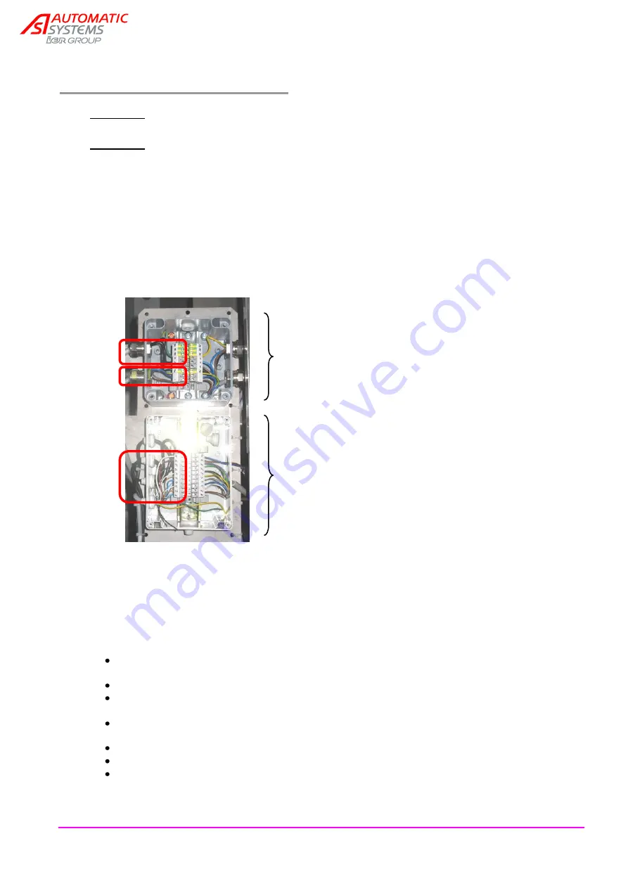
Two intermediate terminal boxes are located beneath the hatch (8, p5):
The cables connecting these two intermediate terminal strips to the control box must be pla ced
in the 2 cable guides (9, p5). The High Voltage cables must be separated from the Low Voltage
cables in order to avoid interference, with the upper cable guide being reserved for the Low
Voltage and the lower cable guide for the High Voltage. The cables should not obstruct the
obstacle’s opening and closing movem ents nor be crushed during those movements.
Turn off the circuit breaker (23, p6) before carrying out the operations described below.
Connect the mains supply to the terminal strip (20, p6), making sure that it is in
conformity with the required specifications (see p 21).
Connect the traffic lights to the terminal strip (20, p 6).
Connect the braking module control (35) to the terminal strip (20, p 6), via the lower cable
guide.
Connect the motor control (36) to the variable speed controller (26, p 6), via the lower cable
guide.
Connect the detection control (37) to the terminal strip (20, p6), via the upper cable guide.
Connect the pushbutton box to terminal strip (20, p6).
Connect any possible options (readers, loops) to the terminal strip (20, p 6) (see electrical
diagram, p25).
33
34
33. Motor / braking module terminal box
(diagram 1RSB7600.006)
34. Detection terminal box
(diagram 1RSB7600.005)
35. Braking module control
36. Motor control
37. Detector control
35
36
37


