background image

Revised 11/6/02 • LGRM-E

2

© 2002 Automated Logic Corporation

Using the LGRM-E

The LGRM-E is part of the Gateway family and 
provides communication between a 
workstation and a control module network 
(CMnet) consisting of fewer than 100 
modules. Up to 199 gateways can be 
networked together on an LGnet, allowing 
the LGRM-Es to route global information 
between CMnets. While the LGRM-E supports 
199 gateways, versions of SuperVision earlier 
than 3.01 do not support more than 60 
gateways.

The LGRM-E provides an Ethernet 10base-T 
port for 10Mbps communication with the 
LGnet. Two console ports that can be 
connected to a workstation, portable 
computer, or modem, an Auxiliary Device 
Port (Keypad/Display Port), and an Access 
Port are also provided.

Console Port 1 is a 9-pin EIA-232 connector. 
Console Port 2 is a 5-pin terminal jumper.

TCP/IP (Transmission Control Protocol/
Internet Protocol) is a family of protocols used 
for computer communications. The LGRM-E 
uses the UDP/IP (User Datagram Protocol/
Internet Protocol) of the TCP/IP family. The 
workstation must be configured to 

communicate with the LGRM-E over TCP/IP 
as discussed in the document 

TCP/IP Setup for 

Windows 95/NT and SVW 2.6

 (Part number 

LGTCPIP).  

The LGRM-E must use v6.00g or later of the 
LEM module driver; for more information, see 
the 

LEM Module Driver 

document on the 

Automated Logic website at
www.automatedlogic.com
or on the SupportPlus CD. 

NOTE

This equipment has been tested and 

found to comply with the limits for a Class A 
digital device, pursuant to Part 15 of the FCC 
Rules. These limits are designed to provide 
reasonable protection against harmful 
interference when the equipment is operated 
in a commercial environment. This 
equipment generates, uses, and can radiate 
radio frequency energy and, if not installed 
and used in accordance with the instruction 
manual, may cause harmful interference to 
radio communications. Operation of this 
equipment in a residential area is likely to 
cause harmful interference in which case the 
user will be required to correct the 
interference at his own expense. 

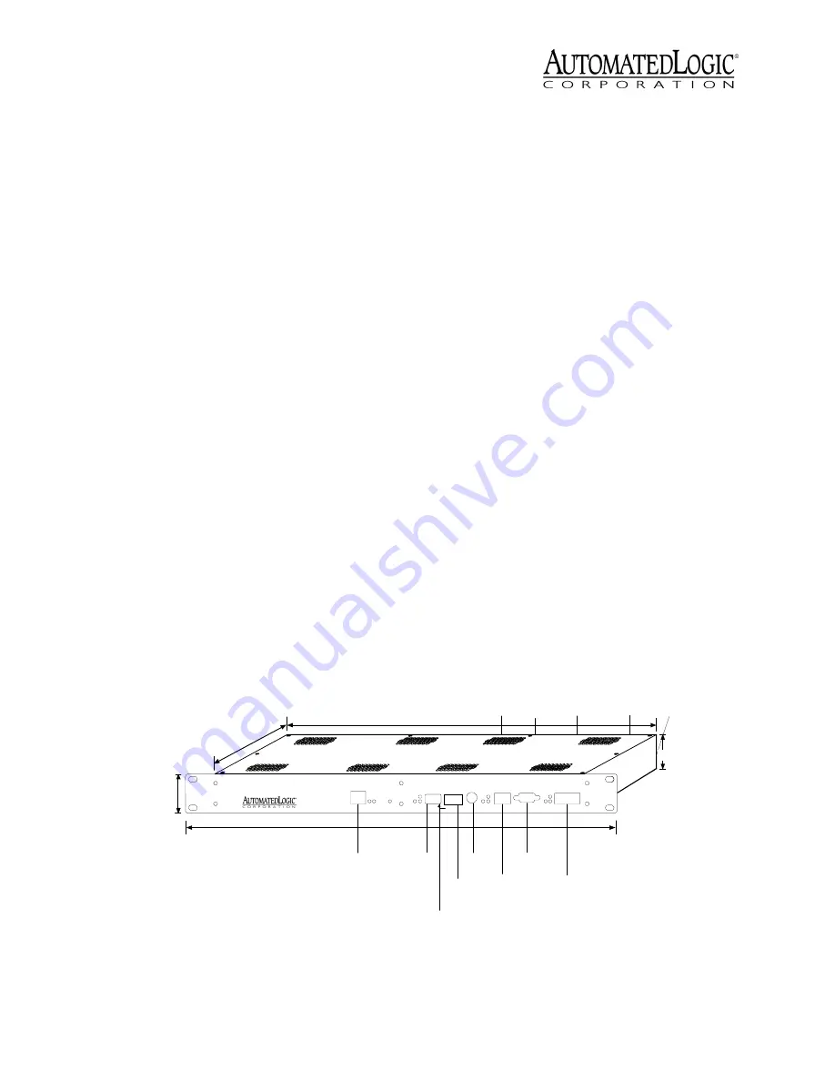
 Figure 1. Module dimensions and layout

1 3/4"

4.45cm

10 3/16"

25.88cm

17"

43.18cm

19 1/16"

48.42cm

Ethernet
10baseT

Port

DIP

Switches

Access

Port

Console

Port 1

Format

Button

Power

Connector

Auxiliary

Device

Port

Auxiliary

Power

Addressing

Rotary

Switches

CMnet

Connection

Console

Port 2

LGRM-E

RJ4 5

10base
T

LI

N

K

L

A

N

E

th

e

rn

e

t

P

o

w

e

r

M

o

d

u

le

P

o

w

e

r

Run

E rror

96

0

0

/3

8

.4

k

b

a

u

d

96

0

0

/3

8

.4

k

b

a

u

d

96

0

0

/3

8

.4

k

b

a

u

d

D

e

fa

u

lt/

A

ss

ig

n

e

d A

R

C

1

5

6

/L

e

g

a

c

y 1

0

0

's

Le

g

a

-

c

yC

o

n

1

C

o

n

2

IP

A

d

d

r

M

o

d

e

LGne t

A ddress

10 's

1' s

A ccess

Por
t

C om
mSta

t

Rx

Tx

CMn
et

CMn
et

Connec-
tion

N

e

t

+

N

e

t

-

S

h

ie

ld

1

D

C

D

2

R

x

3

Tx

4

D

TR

5

G

N

D

N

/

C

6

+

1

0

V

7

N

/C

8 N

/C

9

Console
1

Rx

Com
mSta

t

Tx

Console
2

Console 2

Connec-
tion

T

x

R

x

D

TR

D

C

D

S

ig

n

a

l

G

ro

u

n

d

Connec-
tion

1 25/32"

4.5cm

Power
Switch

Addressing

DIP

Switch

Содержание LGRM-E

Страница 1: ...rOp is a trademark of Automated Logic Corporation BACnet is a registered trademark of ASHRAE All other brand and product names are trademarked by their respective companies Technical Instructions LGRM E Using the LGRM E 2 Specifications 3 Mounting 3 Addressing 3 LGnet addressing 3 IP Addressing 4 Wiring 5 Power Wiring 5 Communications Wiring 5 Initializing the LGRM E 6 Transferring Memory 7 Troubl...

Страница 2: ...e Automated Logic website at www automatedlogic com or on the SupportPlus CD NOTE This equipment has been tested and found to comply with the limits for a Class A digital device pursuant to Part 15 of the FCC Rules These limits are designed to provide reasonable protection against harmful interference when the equipment is operated in a commercial environment This equipment generates uses and can ...

Страница 3: ...s on the faceplate see Figure 1 on page 2 If a rack is not available the LGRM E can be mounted with mounting brackets The LGRM E is designed to be mounted inside the building All warranties are void if mounted outside CAUTION Changes or modifications to this unit not expressly approved by the party responsible for compliance could void the user s authority to operate equipment Addressing LGnet add...

Страница 4: ...ocal network segment Assigned When the IP ADD DIP switch is set to Assigned you must set the above parameters on the LEM Parameter page Default mode Use the following procedure to set the IP address when using the Default mode 1 Set the IP ADD DIP switch to Default 2 Turn the LGRM E s power on 3 If using SuperVision v2 6 edit your HOSTS file to include the following line for each gateway see the T...

Страница 5: ...nect power to the LGRM E 1 Turn off the LGRM E s power switch 2 Connect the terminal strip connector see Figure 4 to the power connector on the back of the LGRM E see Figure 5 on page 6 3 Plug the power adaptor into an outlet 4 Turn the module s power switch on When the module turns on the Run and Power LEDs turn on The Run LED begins blinking and the Error LED turns off See Table 3 on page 10 to ...

Страница 6: ...ame polarity as used throughout the rest of the CMnet 3 Make sure the LGRM E is configured for the correct communication speed Connecting to the LGnet Connect a LAN 10base T cable to the Ethernet port Connecting to a Workstation or Modem Connect the DC95 or DC99 cable to console port 1 or 2 See Communicating with the Workstation on page 7 for more details NOTE The EIA 232 connection should not exc...

Страница 7: ...ver and look at the module status report in SuperVision to make sure the module type and number agree with the module To view the module status report in SuperVision v3 0 click Tools Troubleshooting Module Status To view the module status report in SuperVision v2 6b press the Esc key type MO module address 15 and press Enter 3 Transfer memory to the module In SuperVision v3 0 click Tools Troublesh...

Страница 8: ... Port 9 pin 20 DTR 7 GND 8 DCD 3 RX 2 TX Workstation 25 pin DCD 1 DTR 4 TX 3 RX 2 GND 5 Console Port 9 pin DS R 6 RI 9 CTS 8 RTS 7 8 DCD 20 DTR 2 TX 3 RX 7 GND Modem 25 pin 6 DSR 22 RI 5 CTS 4 RTS G ND 5 TX 1 RX 2 Console Port 5 pin 5 GND 2 RX 3 TX W orkstation 9 pin Console Port 2 DTR 3 20 DTR TX 1 2 TX RX 2 3 RX GND 5 7 G ND Console Port 5 pin DCD 4 8 DCD Modem 25 pin W ire connection usually no...

Страница 9: ... on page 2 for location While continuing to hold the Format button turn the module s power on 3 Continue to hold the button until the Error LED flashes three times in sync with the Run LED 4 Release the Format button 5 Transfer memory to the module Refer to Transferring Memory on page 7 LEDs The LGRM E has several LED indicators to show the status of certain functions Table 3 on page 10 explains t...

Страница 10: ...out the module status report A sticker on the back of the module also shows the date the module was manufactured The first three characters on the sticker indicate the type of module The next three characters show the year month and week of manufacture The month digit is in hexadecimal Table 3 LED Signals Run LED Error LED Condition 2 flashes per second Off Normal 2 flashes per second 1 flash per ...

Отзывы: