


1-4 AutoCAD
®
LT 2000 MultiMedia Tutorial
6. Move the cursor to the left of point 2 and create a horizontal line about the
same length as the first line on the screen.
7. Repeat
step 5 and complete the freehand sketch by adding three more lines
(from point 3 to point 4, then connect to point 5 and back to point 1).
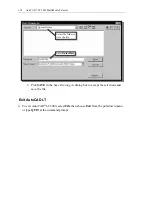
8. Notice that the LINE command remains
activated even after we connected the last
segment of the line to the starting point (point
1) of our sketch. Inside the Graphics window,
click once with the right-mouse-button and a
popup menu appears on the screen.
9. Select
Enter with the left-mouse-button to end
the LINE command. (This is equivalent to
hitting the [Enter] key on the keyboard. The
right-mouse-click brings up more options and
we should get used to using the option menu.)
10. Move the cursor near point 2 and point 3, and
estimate the length of the horizontal line by
watching the displayed coordinates for each
point at the bottom of the screen.
Visual reference
The method we just used to create the freehand sketch is known as the interactive
method, where we use the cursor to specify locations on the screen. This method is
perhaps the fastest way to specify locations on the screen. However, it is rather difficult
to try to create a line of a specific length by watching the displayed coordinates. It would
be helpful to know what one-inch or one-meter looks like on the screen while we are
creating entities. AutoCAD LT 2000 provides us with many tools to aid the construction
of our designs. We will use the GRID and SNAP options to get a visual reference as to
the size of objects and learn to restrict the movement of the cursor to a set increment on
the screen.
The Status Bar area is located at the bottom of the AutoCAD LT Drawing Screen. The
words SNAP, GRID, ORTHO, POLAR, OSNAP, LWT and MODEL appearing to the
right of the coordinates are buttons that we can left-click to turn these special options ON
and OFF. When the corresponding button is highlighted, the specific option is turned on.
These buttons act as toggle switches; each click of the button will toggle the option on or
off. Using the buttons is a quick and easy way to make changes to these Drawing Aid
options. We can toggle the options on and off in the middle of another command.