Section 03
ENGINE
Subsection 09
(CYLINDER AND HEAD)
VMR2004_132_03_09A.FM
03-09-19
CAUTION:
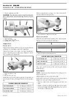
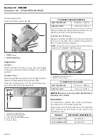
Push valve guide
no. 40
in the cold
cylinder head as per following illustration.
1. Thrust surface of cylinder head
2. Valve guide
A. Measurement from thrust surface to valve guide top
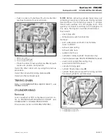
Valve guide to be adjusted in diameter by using a
reamer.
1. Valve guide
A. Valve guide diameter
NOTE:
Ensure to turn reamer in the right direc-
tion. Use cutting oil and make brakes to clean
reamer/valve guide from metal shavings.
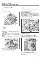
Apply some lapping compound to valve face and
work valve on its seat with a lapping tool.
1. Valve seat
2. Valve face (contact surface to valve seat)
3. Turn valve while pushing against cylinder head
A. Valve seat angle 45°
NOTE:
Ensure to seat valves properly. Apply
marking paste to ease checking contact pattern.
Repeat procedure until valve seat/valve face fits
together.
CYLINDER
Removal
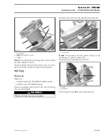
Lock crankshaft at TDC compression position, re-
fer to CRANKSHAFT/BALANCER SHAFT, see
CRANKSHAFT LOCKING PROCEDURE.
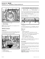
Using the camshaft locking tool (P/N 529 035 926),
lock the camshaft at TDC compression position to
prevent timing chain stretching.
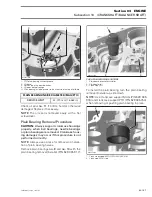
Remove:
– chain tensioner
(see CHAIN TENSIONER
above)
– decompressor
– camshaft timing gear
– cylinder head (see CYLINDER HEAD
above).
VALVE GUIDE MEASUREMENT A
NEW MINIMUM
14.00 mm (.5512 in)
NEW MAXIMUM
14.40 mm (.5669 in)
VALVE GUIDE DIAMETER
NEW MINIMUM
EXHAUST
5.006 mm (.1971 in)
INTAKE
NEW MAXIMUM
EXHAUST
5.018 mm (.1976 in)
INTAKE
1
R400motr87B
2
A
R400motr88A
1
A
A
R400motr89A
1
2
3
Содержание M-50 x 4
Страница 1: ...1 AUSA M 50 x 4 ROTAX ENGINE WORKSHOP MANUAL ...
Страница 2: ......
Страница 3: ......
Страница 7: ......
Страница 27: ......
Страница 31: ......
Страница 59: ......
Страница 85: ......
Страница 99: ......
Страница 136: ...Section 04 FUEL SYSTEM Subsection 03 CARBURETOR VMR2004_137_04_03A FM 04 03 1 CARBURETOR 0 V07F0ZS Harness assembly ...
Страница 147: ......
Страница 155: ......


