Section 03
ENGINE
Subsection 09
(CYLINDER AND HEAD)
03-09-14
VMR2004_132_03_09A.FM
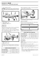
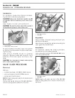
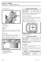
Measure clearance between both ends of cam-
shaft and cylinder head.
A. Cylinder head — camshaft bore MAG side
B. Cylinder head — camshaft bore PTO side
Replace parts that are not within specifications.
Installation
For installation, reverse the removal procedure.
Pay attention to the following details.
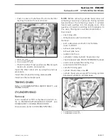
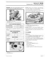
Install camshaft in the opposite way of the remov-
al then place the camshaft retaining plate in the
slot.
1. Camshaft retaining plate position
2. Slot retaining camshaft
3. Direction of movement
For other parts, refer to proper installation proce-
dure.
VALVE SPRING
Removal
Remove:
– rocker arms (see ROCKER ARM
above)
– cylinder head (see CYLINDER HEAD
above).
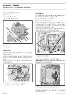
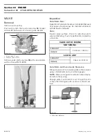
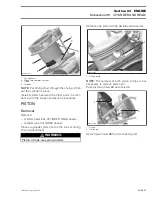
Compress valve spring
no. 33
; use valve spring
compressor clamp (P/N 529 035 724) and valve
spring compressor cup (P/N 529 035 725).
CAMSHAFT BORE — MAG SIDE
MEASURED IN DIAMETER
NEW MINIMUM
35.000 mm (1.3780 in)
NEW MAXIMUM
35.025 mm (1.3789 in)
SERVICE LIMIT
35.040 mm (1.3795 in)
CAMSHAFT BORE — PTO SIDE
MEASURED IN DIAMETER
NEW MINIMUM
22.000 mm (.8661 in)
NEW MAXIMUM
22.021 mm (.8670 in)
SERVICE LIMIT
22.040 mm (.8677in)
R400motr77A
A
B
WARNING
Always wear safety glasses when disassem-
bling valve springs. Be careful when unlock-
ing valves. Components could fly away be-
cause of the strong spring preload.
R400motr75B
3
1
2
Содержание M-50 x 4
Страница 1: ...1 AUSA M 50 x 4 ROTAX ENGINE WORKSHOP MANUAL ...
Страница 2: ......
Страница 3: ......
Страница 7: ......
Страница 27: ......
Страница 31: ......
Страница 59: ......
Страница 85: ......
Страница 99: ......
Страница 136: ...Section 04 FUEL SYSTEM Subsection 03 CARBURETOR VMR2004_137_04_03A FM 04 03 1 CARBURETOR 0 V07F0ZS Harness assembly ...
Страница 147: ......
Страница 155: ......


