Section 03
ENGINE
Subsection 05
(COOLING SYSTEM)
VMR2004_128_03_05A.FM
03-05-11
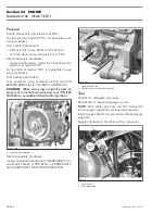
1. Radiator mounting bolts
Unplug temperature sender connector
no. 18
then remove the radiator
no. 13
.
Inspection
Check radiator air passage for clogging or damage.
Remove insects, mud or other obstructions with
compressed air or low pressure water.
Check for any coolant leakage from radiator and
hoses.
Installation
For installation, reverse the removal procedure. Pay
attention to the following detail.
Fill up the radiator. Refer to the COOLANT RE-
PLACEMENT PROCEDURE, at the beginning of
this section.
COOLANT TANK
Overflow Coolant Tank
The coolant expands as the temperature (up to
100 - 110°C (212 - 230°F)) and pressure rise in the
system. If the limiting system working pressure
cap is reached 110 kPa (16 PSI), the pressure relief
valve in the pressure cap is lifted from its seat and
allows coolant to flow through the overflow hose
into the overflow coolant tank
no. 15
.
Removal
Remove:
– LH inner fender (refer to BODY)
– coolant tank support bolt
no. 19
– overflow hose
no. 12
– coolant tank
no. 15
.
Empty coolant tank.
Installation
The installation is the reverse of the removal pro-
cedure.
COOLING FAN
Test
NOTE:
No key required for this test.
Unplug the temperature sender connector.
Install a jumper wire end in connector. Replace the
cooling fan
no. 20
if it does not work.
Removal
Remove both inner fenders. Refer to BODY.
Unplug cooling fan connector.
Remove bolts
no. 21
.
Remove the cooling fan.
Installation
For the installation, reverse the removal procedure.
1
V07C0RA
V07C0SA
Содержание M-50 x 4
Страница 1: ...1 AUSA M 50 x 4 ROTAX ENGINE WORKSHOP MANUAL ...
Страница 2: ......
Страница 3: ......
Страница 7: ......
Страница 27: ......
Страница 31: ......
Страница 59: ......
Страница 85: ......
Страница 99: ......
Страница 136: ...Section 04 FUEL SYSTEM Subsection 03 CARBURETOR VMR2004_137_04_03A FM 04 03 1 CARBURETOR 0 V07F0ZS Harness assembly ...
Страница 147: ......
Страница 155: ......


