AUMA Riester GmbH & Co. KG
Location Ostfildern-Nellingen
Postfach 1151, DE 73747 Ostfildern
Tel +49 711 34803 – 0
Fax +49 711 34803 - 3034
AUMA Industry & Marine GmbH, 12.2021
Y009.324/001/de-en/1.21
Seite/page 1/2
EQ15-600: Nachrüsten von Positionselektronik /
EQ15-600: Retrofitting of Positioner
Einbau wie folgt:
Falls im Antrieb kein Potentiometer vorhanden ist, muss dieses zuerst nachgerüstet werden.
Montage Potentiometer
Winkel [1] mit Kondensator abschrauben.
Falls der Antrieb über eine Heizung verfügt, ist das Potiblech [4.9.3] bereits im Antrieb vorhanden und kann für die
Potentiometermontage verwendet werden.
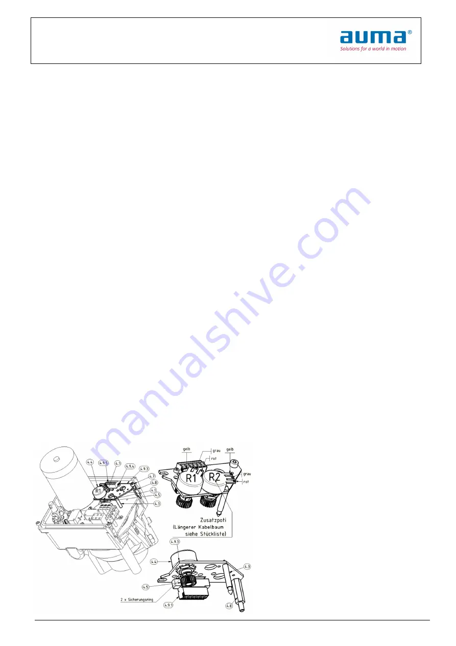
Potentiometer R1 [4.4] ins Potiblech [4.9.3] einsetzen und mit Zahnscheibe und Mutter befestigen. 2 Sicherungsrin-
ge auf Potiritzel [4.5] aufsetzen und Potiritzel auf die Potentiometerwelle [4.4] aufstecken. Potileitung am Potentio-
meter anlöten, durch die Bohrung Ø8 nach unten führen und am Stecker Unterteil [4.9.5] rot-28, grau-29, gelb-30
anklemmen. Stecker Unterteil [4.9.5] mit Innensechskantschrauben M2,5x6 [4.9.4] an Potiblech [4.9.3] anschrau-
ben. Abstandshalter [4.3] ins Potiblech [4.9.3] einklipsen. Innensechskantschraube am Getriebedeckel durch Ab-
standsbolzen M4x22 [4.8] ersetzen. Potiblech [4.9.3] in den Antrieb einsetzen, Abstandshalter [4.3] im Getriebede-
ckel einklipsen, und mit Innensechskantschraube M4x6 [4.7] am Abstandsbolzen M4x22 [4.8] anschrauben. Ver-
zahnungsspiel durch leichtes Schieben der Potibaugruppe an Potirad/Nockenwelle beim Anschrauben herausdrü-
cken.
Assembly as follows:
If the actuator does not have a potentiometer inside, it has to be retrofitted first.
Assembly potentiometer
Remove capacitor holder [1].
If the actuator is equipped with a heater, the potentiometer retaining plate [4.9.3] is already inside and can be used
for potentiometer assembly.
Put potentiometer R1 [4.4] into retaining plate [4.9.3] and fasten with a lock washer and nut. Put 2 locking rings on
the pinion [4.5] and put the pinion on the potentiometer shaft. Solder wiring harness on the potentiometer, put it
through the hole Ø8 down and connect to the lower part of the connector [4.9.5] (red-28, gray-29, yellow-30). Screw
the lower part of the connector [4.9.5] with allen screws M2, 5x6 [4.9.4] to retaining plate [4.9.3]. Clip the spacer
[4.3] into retaining plate [4.9.3]. Replace the allen screw on the gear cover by distance bolt M4x22 [4.8]. Insert re-
taining plate [4.9.3] into the actuator, clip spacer [4.3] in the gear cover, and fasten it with allen screw M4x6 [4.7] on
the spacer bolt M4x22 [4.8]. To eliminate backlash push the retaining plate [4.9.3] gently in the direction of the cam-
shaft while screwing.


