2
ATW-T94 UHF Handheld Microphone / Transmitter
Audio-Technica Engineered Sound
¨
wireless systems
are offered as separate receiver and transmitter units,
rather than in predetermined combinations, for greatest
system flexibility . Operating details for Engineered
Sound receivers and overall system operation are
included with each receiver.
Engineered Sound receivers feature a sophisticated
Tone Lock
ª
tone squelch system that opens only when
an Engineered Sound transmitter is detected, reducing
the possibility of interference. As a result, Engineered
Sound transmitters and receivers must be used
together and should not be used with components
from other Audio -Technica wireless systems, or with
those of other manufacturers.
Please note that in multiple-system applications there
must be a transmitter -receiver pair set to a separate
frequency for each input desired (only one transmitter
at a time for each receiver). Because the wireless
frequencies are on UHF TV frequencies, only certain
wireless frequencies may be useable in a particular
geographic area. Also, only certain of the available
operating frequencies may be used together.
Introduction
Battery Selection and Installation
The transmitter uses two 1.5V AA batteries, not
included. Alkaline type is recommended. Always
replace both batteries.
Make certain the transmitter
power switch is turned Off before replacing
batteries.
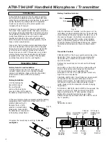
Battery Installation
1. While holding the
transmitter body at
the on-off switch,
unscrew the lower body
cover and slide it off to expose
the battery compartment (Fig. A).
Fig. A
Transmitter Setup
Fig. B
Fig. C
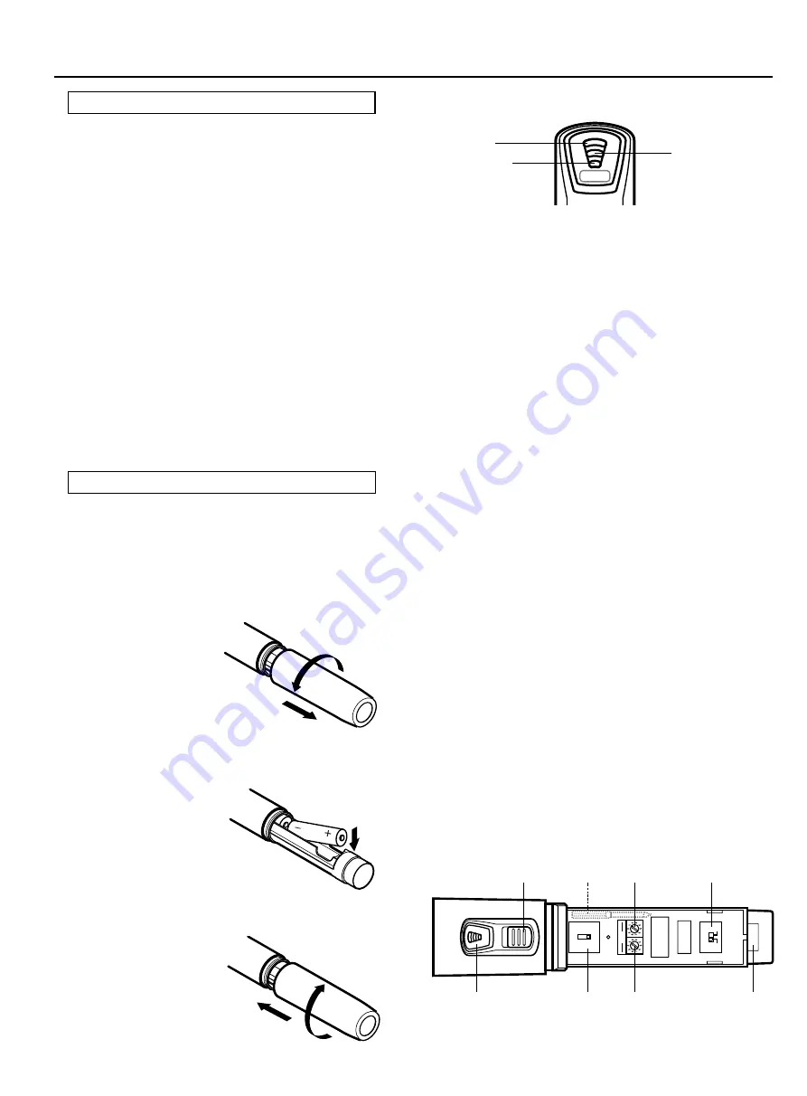
Battery Condition Indicator
After the batteries are installed, turn the power on. The
red battery condition indicator LED (Fig. D) should flash
momentarily and the green indicator should come on. If
this does not happen, the batteries are installed incor-
rectly or they are dead. If the yellow or red indicator
stays on, the battery voltage is low and the batteries
should be replaced. If this happens during use, replace
the batteries immediately to ensure continued opera-
tion.
Fig. D
BATT
ON
Green
Red
Yellow
2.
Observe correct polarity as marked inside the battery
compartment
and carefully insert two fresh 1.5V AA
alkaline batteries(Fig. B).
Because there is some
variation in actual battery
dimensions, make centain
the batteries are
fully
seated
in the battery compartment.
3. Replace the lower body cover (Fig. C).
Do not
overtighten.
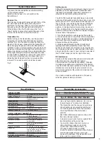
Transmitter Controls
POWER SWITCH: The Power switch controls the entire
transmitter. There is about a half-second delay after
transmitter turn-on before the receiver's Tone Lock
squelch un-mutes.
Remove the lower body cover to access the following
controls.
PAD SWITCH: The ATW -T94 offers a Pad switch with
0/-6/-12 dB positions which increases the maximum
SPL (sound pressure level) capability of the
microphone. Use the "0" (no pad) position unless very
high SPLs are encountered.
CHANNEL SWITCHES: The left channel selector switch
corresponds to the receiver's left-column channel
display number (tens); the right switch corresponds to
the receiver's right-column channel display number
(units). Always turn the transmitter off when changing
frequencies.
RF POWER / BATTERY-SAVE SWITCH: As supplied, the
switch is set in the "H" (high) position for maximum
range. Switching to the "L" (low) position increases
battery life somewhat by reducing power. (Note:
Effective range may decrease when the switch is set at
the "L" position.)
Fig. E
Transmitter Controls
BA
T
T
ON
RF
PO
W
ER
H
L
PA
D
(dB
)
-6 0
-1
2
CH
Battery
Condition
Indicator
Pad
Switch
Channel
Switch
x10
Power
Switch
Channel
Switch
x1
RF Power/
Battery-Save
Switch
Screwdriver
Storage
Serial
Number


