background image

Audio International, Inc.


                  VCP-010-06(-07)-x Installation & Operation Manual 


Document # 540236, Rev IR, 11/2002  


Page 13 of 21 

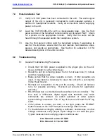
7.0     Post-Installation Test 


7.1 

28 VDC power has been connected to the unit.  The audio signal 
output of the unit is generally connected to cabin speaker systems in 
addition to headphone locations.  Verify all connections before supplying 
power to the unit. 

 
7.2  Load the VCP-010-06(-07)-x with a videocassette tape.  Use the front 

panel controls or the hand-held remote control unit to select PLAY.  Check 
for a picture on the appropriate monitor.  Verify that the audio can be 
heard through the speaker and/or the headphone system. 
 

7.3 

Use the front panel controls (and the hand-held remote, if applicable) to 
each of the functions; ensure that the unit rewinds, fast-forwards, stops, 
pauses, and ejects as appropriate.  See Section III, subsection 3.0 for 
detailed descriptions of the units’ controls. 


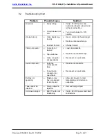
8.0   Troubleshooting 
 

8.1 General 

Troubleshooting 

Procedures 


• 

Check that +28 VDC power is applied to the proper pins on the unit.  
Use a voltmeter to verify correct level. 

• 

Reset the unit by removing power from it for at least one (1) minute 
and then reapply power. 

• 

Make certain that the video cassette is clean.  If dirty cassettes are 
used, it may become necessary to clean the unit with a commercial 
Video Head Cleaner. 

• 

Recheck all connections to the unit for security.  Check all harness 
runs for possible pinching.  Recheck all pinouts for application 
accuracy. 

• 

RS-485 data bus is a bi-directional bus without a “bus controller.”  The 
bus uses a differential digital signal that transmits only when 
commands are entered via switch selection or other system 
synchronizing commands.  The “A” leg of the bus is HI and the “B” leg 
LOW. 

• 

If the picture is unclear, too dark, or too light, press the FORMAT 
button located on the VCP front panel to change video formats. 

• 

To check data bus integrity, utilizing a voltmeter, oscilloscope, or other 
voltage instrument, verify proper input voltage on the data bus pins. 
Typical measurements verifying proper conditions are: 


A to Ground : 4.0 to 4.5 VDC 

    B to Ground : 0.1 to 0.2 VDC


Содержание VCP-010-06-1 VCP-010-06-2

Страница 1: ...00 Industry Drive North Little Rock AR 72117 Phone 501 955 2929 Fax 501 955 2988 www audiointl com Installation and Operation Manual VCP 010 06 07 x Multi Standard Video Cassette Player Document 54023...

Страница 2: ...Revision Revision Date Table of Illustrations Section Subsection Description Page I 6 2 Typical Application 6 7 II 9 1 Reference Drawings VCP 010 06 x 15 16 II 9 2 Reference Drawings VCP 010 07 x 17...

Страница 3: ...al Equipment 5 5 0 Technical Specifications 5 6 0 Application 5 II INSTALLATION 8 1 0 Prior to Installation 8 2 0 Unpacking and Inspection 8 3 0 Cautions Warnings 9 4 0 Wiring Requirements 10 5 0 Phys...

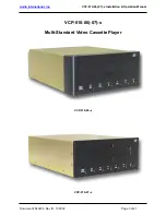
Страница 4: ...Audio International Inc VCP 010 06 07 x Installation Operation Manual Document 540236 Rev IR 11 2002 Page 3 of 21 VCP 010 06 07 x Multi Standard Video Cassette Player VCP 010 06 x VCP 010 07 x...

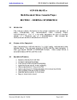
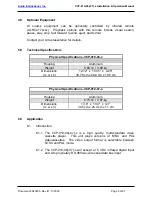
Страница 5: ...cal characteristics of the unit 2 0 Purpose of the Equipment Audio International s VCP 010 06 07 x is a high quality multi standard video cassette player This unit plays versions of NTSC and PAL video...

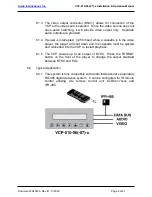
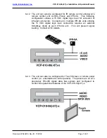
Страница 6: ...uction 6 1 1 The VCP 010 06 07 x is a high quality multi standard video cassette player This unit plays versions of NTSC and PAL videocassettes The video output format is selectable between NTSC and P...

Страница 7: ...s interrupted 250 msec while a cassette is in the video player the player will shut down and the cassette must be ejected and reinserted into the VCP to restart playback 6 1 5 The VCP powers up to an...

Страница 8: ...level for activation of infrared commands Connection to multiple IFR 9A units utilizing the 5 VDC digital logic level connection requires an external Schottkey diode at each IFR 9A unit This will prev...

Страница 9: ...g conditions as to the unit location and type of installation 1 3 Mounting screws are required to secure the unit Refer to Section II 9 0 for mounting hole diameters and configurations 1 4 All headpho...

Страница 10: ...or ground is applied to the wrong points 3 2 DO NOT connect or disconnect the unit while power is applied 3 3 DO NOT remove any factory installed screws Damage to the unit may result and void any warr...

Страница 11: ...parallel to combustible fluid or oxygen lines maintain a minimum separation of six 6 inches between the lines 4 2 Power Wires All power and ground wires shall be 22 AWG MINIMUM shielded twisted pair w...

Страница 12: ...pecification is available upon request 5 0 Physical Characteristics 5 1 Refer to Section I 5 0 for unit dimensions and Section II 9 0 for attachment points 5 2 When mounting the unit allow sufficient...

Страница 13: ...evices when using the RS 485 data bus to be used in the same system while maintaining independent control Three 3 strap pins are available to configure the infrared codes and RS 485 addressing Standar...

Страница 14: ...ooting Procedures Check that 28 VDC power is applied to the proper pins on the unit Use a voltmeter to verify correct level Reset the unit by removing power from it for at least one 1 minute and then...

Страница 15: ...lace videocassette tape Change Format Video not present Cassette not loaded Tape defective Video connector not operational Load videocassette Replace videocassette tape Reconnect or repair cable Audio...

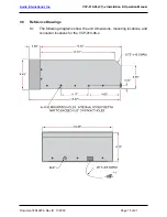
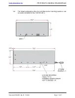
Страница 16: ...010 06 07 x Installation Operation Manual Document 540236 Rev IR 11 2002 Page 15 of 21 9 0 Reference Drawings 9 1 The following diagrams show the unit dimensions mounting locations and connector loca...

Страница 17: ...Audio International Inc VCP 010 06 07 x Installation Operation Manual Document 540236 Rev IR 11 2002 Page 16 of 21...

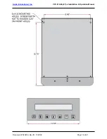
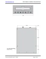
Страница 18: ...onal Inc VCP 010 06 07 x Installation Operation Manual Document 540236 Rev IR 11 2002 Page 17 of 21 9 2 The following diagrams show the unit dimensions mounting locations and connector locations for t...

Страница 19: ...Audio International Inc VCP 010 06 07 x Installation Operation Manual Document 540236 Rev IR 11 2002 Page 18 of 21...

Страница 20: ...frared inputs or eight 8 of the same devices when using the RS 485 data bus to be used in the same system while maintaining independent control Three 3 strap pins are available to configure the infrar...

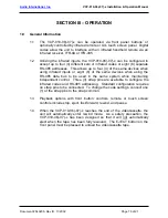
Страница 21: ...into the Tape Slot 2 1 Gently insert a videocassette tape into the cassette tape slot Apply slight forward pressure to the side edge of the tape The VCP 010 06 07 x will gently pull the tape into the...

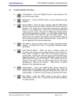
Страница 22: ...f the videocassette tape 3 4 Play Button Press the PLAY button to begin videocassette tape viewing Pressing PLAY twice in succession activates double speed play 3 5 Fast Forward Button While the tape...

Отзывы: