4
5
3.0 INSTALLATION
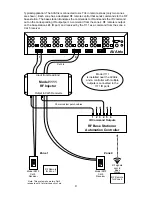
Follow the diagram carefully, and
use only the supplied cables
. The RF base
station should have at least as many IR outputs as the number of zones with
dedicated RF controllers; for example, in an application with six RF remotes, the
controller should have at least 6 IR outputs.
•
Test all Cat 5 cables with a network cable tester,
even factory-terminated
cables.
Continuity testing is not adequate. Cables must have the
correct
pairing
or damage could result. Use either EIA-568A or EIA-568B conductor
pairing throughout the system.
• Use only the custom 3.5mm cables included. Other cables may cause damage
to the AVAtrix by allowing DC power to be injected into the system.
• Place the Model 1111 near the AVAtrix and connect each numbered Cat 5/6
port on the AVAtrix to the same-numbered Input port on the 1111, using short
Cat 5 patch cords.
• Multiple 1111 Control Bridges may be used in one system to serve up to 36
zones. Install one Model 1111 for each set of six AVAtrix Cat 5 outputs.
• Plug the RF base station or automation controller into the 3.5mm IR Input
jacks on the 1111.
3.1 PROGRAMMING
Each RF base station output should be individually assignable to an individual
RF remote in the remote software. Program the remote for zone 1 to output IR on
the base station’s #1 output, zone 2 remote on the #2 output, etc.
Load the remote with codes for each device to be controlled as well as the codes
for the AVAtrix. The only AVAtrix commands required are buttons 1 through 6. If
you are using the AVAtrix temporary restriction features, add the commands for
Lock, View-lock, IR-lock and Unlock.
Example macro
To watch source #1:
Send “1” key from AVAtrix remote codes.
Send DVD Power On command.
Send DVD Play command.
4.0 TROUBLESHOOTING
• If signals are intermittent between the 1111 and the AVAtrix or if the IR path
isn’t operating correctly, check the integrity of the Cat 5 cables and the wiring
of their plugs with a network cable tester.
• Check that cables are plugged into the correct jacks.
• If a problem persists contact the Audio Authority Technical Service
department via email: [email protected], or call 800-322-8346 or
859-233-4599.


