Multi Channel Transmitter
(MCTX-16) Installation Instructions
Страница 1: ...Multi Channel Transmitter MCTX 16 Installation Instructions ...
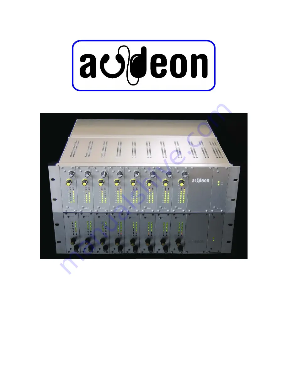
Страница 2: ...ress system Mono and stereo input modules can be mixed in the same processor if required The baseband processor is housed in a standard19 card frame with all electronics on removable cards 1 RF 16 or RF6 Input modules with volume control and bargraph display 2 RF 5 VHF Output amplifier and filters EM 1 Alarm and microphone card EM 2 Emergency message card 3 RF 9 PSU card with fuses and status LEDs...
Страница 3: ...e impaired by a radiated signal in the band 27MHz to 500MHz with a signal strength 3V m and with 80 modulation 3 The AC power input current harmonics arewithin the limitsset by EN 60 555 3 3 The conducted RF emissions are belowthe limits described in EN55 022 class B Council Directive 73 23 EEC The Low Voltage Directive as amended by Article 13 of Council Directive 93 68 EEC Council Directive 1999...
Страница 4: ...tereo System Zenith GE with 19 kHz pilot tone Channel separation 60 dB Radio Output level 0 dBm 1 mW Output impedance 50 Ohms Modulation system FM Maximum deviation for 0 dBu audio input 50 kHz Maximum RF bandwidth per channel 150 kHz Frequency stability 1A0 kHz RF output auto mute time After 5 minutes of no audio input signal Radio Frequencies ISM licence free band UHF channel 70 Channel 1 863A10...
Страница 5: ...cent to the aerial wave aerial Half wave dipole tuned to 864 MHz Feeder cable A 1 metre low loss cable to connect the aerial to the up converter Mains lead Set of installation instructions Service leaflet service price list FAQs Please leave these with the customer Should any part be missing please contact your supplier for a replacement The up converter feeder cable and aerial havebeen tuned in t...
Страница 6: ... dB per metre The aerial will need to be connected to the aerial socket located on the end of the up converter using the BNC feeder cable supplied Do not be tempted to cut the length of or replace the feeder cable as this is tuned in the factory for the best output signal Changing the cable or altering its length will seriously degrade the performance of the system and may cause it to fail to meet...
Страница 7: ...up converter will occur and harmonics and intermodulation will be produced which will cause noise distortion and non compliance with the standards Connect the attenuator and the FC cable to the up converter For the best performancethe attenuator must be at the up converter end of the FM cable so that it masks any impedance miss match and reduces any RF pick up in the cable run With the aerial conn...
Страница 8: ...f your spectrumanalyserhas the facilityto save the results do so as this will show that you have exercised due diligence when setting up the system It is the responsibility of the installer to ensure that the installed system fully complies with all the technical requirements of the R TTE directive Connecting the audio signals The audio input signals should be connected to the two phono sockets fo...
Страница 9: ...pin 1 screen pin 2 microphone phase pin 3 microphone phase pins 4 and 5 are for the mic switch The muting of the audio channels can also be voice activated by speech on the microphone channels To select this option withdraw the mic card from the frame and move the jumper link Internal settings RF16 module The transmitter leaves the factory with the channels set to the frequencies requested by the ...
Страница 10: ...LED bargraphs and it should not exceed 0dB so that the transmitter is not over modulated Check the transmitter output using a receiver and listen to see that the audio signals are muted and the emergency message is played The standard message is Attention please attention please this is an emergency Please leave the building calmly by the nearest exit Do not use the lifts The microphone gain is se...
Страница 11: ...metres from the aerial depending on the layout of the building and objects within the room Check for dead spots which may be caused by obstructions such as metal pillars cupboards or steel work which are in the line of sight of the transmitter or are causing reflections If you do have some areas of poor signal reception consider moving the receiver a small distance is all that may be required or i...
Страница 12: ...issing the upconverter is faulty so obtain a replacement You may see an RF signal on the spectrum analyser but it is the wrong frequency this will indicate that the PLL for the local VCO is not locked obtain a replacement upconverter Please note that the upconverter feeder cable and aerial are all tuned in the factory so they should be changed as a set This can be caused by either the PLL in the u...
Страница 13: ...es coverage over a greater distance compared to a stereo system Check the signal strength with the test aerial and spectrum analyser If it is poor check the output of the upconverter which should be 0dBM remember to use a 20 dB attenuator at this point to protect the analyser If it is correct then increase the height of the transmitter aerial or re site it Low ceilings may also cause this problem ...
Страница 14: ...ment The operator should be made aware of the benefits of expert adviceandsupport Thetelephone line is staffed by experienced engineerswho arefamiliarwith the Audeon range of products They can provide advice on line help and will arrange for maintenance from you the dealer if required A poster is provided with the help line telephone number for display on the staff notice board User Instruction Be...
Страница 15: ...sterboard partition double layer Chipboard partition double layer Window 4 mm glass Window 4 mm polycarbonate Appendix iii Extract from ETSI EN 301 357 Technical characteristics and test methods for analogue cordless wideband audio in the 863 MHz to 865 MHz frequency range Section 8 Methods of measurement and limits for transmitter parameters 8 1 3 Frequency error limit 40 KHz 8 2 3 Carrier power ...
Страница 16: ...Audeon products are designed by John Varley and are manufactured in the UK by M Jay Electronics Limited Albion Mills Church Street Morley Leeds LS27 8LY Phone 44 113 252 4956 Fax 44 113 252 5542 Service 44 113 252 5582 e mail to service audeon co uk www audeon co uk www m jay co uk audeon ...