PROFESSIONAL AUDIO EQUIPMENT
Dual Channel Power Amplifier
D2 – D3 – D4 – D5
User Manual &
Installation Guide
Power Amplifier
AUDAC
Страница 1: ...PROFESSIONAL AUDIO EQUIPMENT Dual Channel Power Amplifier D2 D3 D4 D5 User Manual InstallationGuide PowerAmplifier D2 D3 D4 D5 AUDAC ...
Страница 2: ...A U D A C P R O F E S S I O N A L A U D I O E Q U I P M E N T User Manual Installation Guide AUDAC http www audac be info audac be ...
Страница 3: ...NT AND REAR PANEL 6 FRONT PANEL OVERVIEW 6 FRONT PANEL DESCRIPTION 6 REAR PANEL OVERVIEW 7 REAR PANEL DESCRIPTION 7 CONNECTING THE AMPLIFIER 9 INPUT CONNECTIONS 9 OUTPUT CONNECTIONS 11 CONNECTION STANDARDS 12 ADDITIONAL INFORMATION 13 TECHNICAL SPECIFICATIONS 13 PERSONAL NOTES 14 Index ...
Страница 4: ...ers wanted to achieve three goals Easy to use Excellent sound quality Modern and advanced design AUDAC s D series professional power amplifiers are suitable for the most common low impedance high power sound systems The amplifiers are built as a 2 channel amplifier The amplifiers are equipped with a multipurpose protection circuit which detects DC malfunction short circuit overheating and signal o...
Страница 5: ...Do not block the ventilation openings Do not place the unit in environments which contain high levels of dust heat moisture or vibration Do not use the unit near water or other liquids Make sure no water or other liquids can be spilled dripped or splashed on the unit Do not place objects on top of the unit Place the unit on a stable base Chapter 1 ...
Страница 6: ... the openings of the D2 D3 D4 D5 Do not open the unit risk for electrical shock Always read the user manual before getting started CAUTION SERVICING This unit contains no user serviceable parts Refer all servicing to qualified service personnel Do not perform any servicing unless you are qualified to do so Note This product conforms to the following European Standards EN 50081 1 1992 EN 50082 1 19...
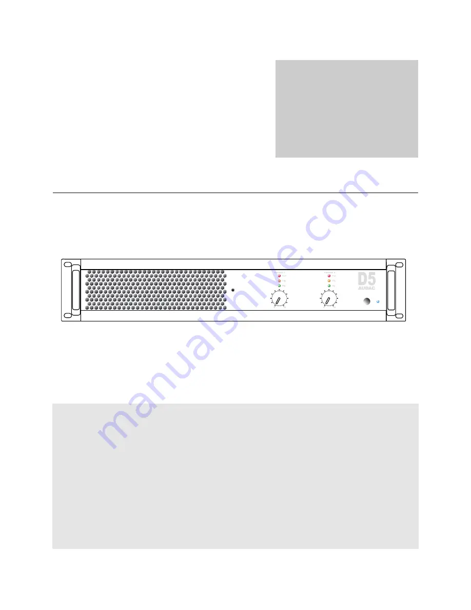
Страница 7: ...fier There are three LED s provided A signal indicator a Clip indicator and a Protect indicator The green signal indicator LED will illuminate when a signal is available on the corresponding channel The yellow clip LED will illuminate when the channels output is being overdriven and the red protection indicator will illuminate when the protection circuit of the corresponding channel is activated T...
Страница 8: ...ns are performed using Speakon connectors For standard stereo applications the loudspeakers should be connected to the 1 and 1 terminals of the Speakon connectors More information about the connection possibilities can be found in the next chapter connecting the amplifier 6 Input connections The input connections of the amplifier are performed using balanced XLR connectors Every channel has an XLR...
Страница 9: ...s switch should be turned to the left position When using in bridged mode the power of both channels will be merged with each other and this switch should be turned to the right position 8 Ground lift switch By means of this switch the ground of the amplifier can be detached to interrupt ground loops This can be useful when unwanted hum and buzz is caused by current flow along the cable shield bet...
Страница 10: ...peration mode switch the operational mode for the amplifier can be selected between Stereo mode and Bridge mode The diagrams below show the connection possibilities for both Stereo and Bridge mode 1 Stereo Mode This is the default mode of how the amplifier is set in the factory and will be the most common used setting for most applications Left position of the switch Connect both outputs from the ...
Страница 11: ...tion mode switch should be positioned in the Bridge position Right position of the switch The output of the signal source should only be connected with the Channel 1 XLR input connector of the amplifier For more information about how the loudspeakers should be connected in bridge mode refer to the Output Connections section of this user manual ...
Страница 12: ...d 2 contain the signal for output Channel 2 The contacts of Speakon 2 Channel 2 only contain the signals of Channel 2 which are available on contacts 1 and 1 Speakon 1 Channel 1 Speakon 2 Channel 2 Pin 1 Channel 1 Channel 2 Pin 1 Channel 1 Channel 2 Pin 2 Channel 2 n c Pin 2 Channel 2 n c 1 Stereo Mode Stereo mode will be the most common operation method for this amplifier The loudspeakers of each...
Страница 13: ...terminal of Channel 1 and the terminal of Channel 2 This can be done by connecting the loudspeaker between the 1 and 2 terminals of Speakon connector one Connection standards The in and output connections of AUDAC audio equipment are performed corresponding to international wiring standards for professional audio equipment XLR 1 ground shield 2 sig 3 sig XLR female XLR male ...
Страница 14: ...2 n a RMS Power 8 Ω D3 2 x 300 W RMS Power 4 Ω D3 2 x 450 W RMS Power 8 Ω Bridged D3 1 x 900 W RMS Power 4 Ω Bridged D3 1 x 1200 W RMS Power 8 Ω D4 2 x 400 W RMS Power 4 Ω D4 2 x 600 W RMS Power 8 Ω Bridged D4 1 x 1200 W RMS Power 4 Ω Bridged D4 1 x 1600 W RMS Power 8 Ω D5 2 x 500 W RMS Power 4 Ω D5 2 x 750 W RMS Power 8 Ω Bridged D5 1 x 1500 W RMS Power 4 Ω Bridged D5 1 x 2000 W Protection DC Sho...
Страница 15: ...14 Personal Notes ...