12
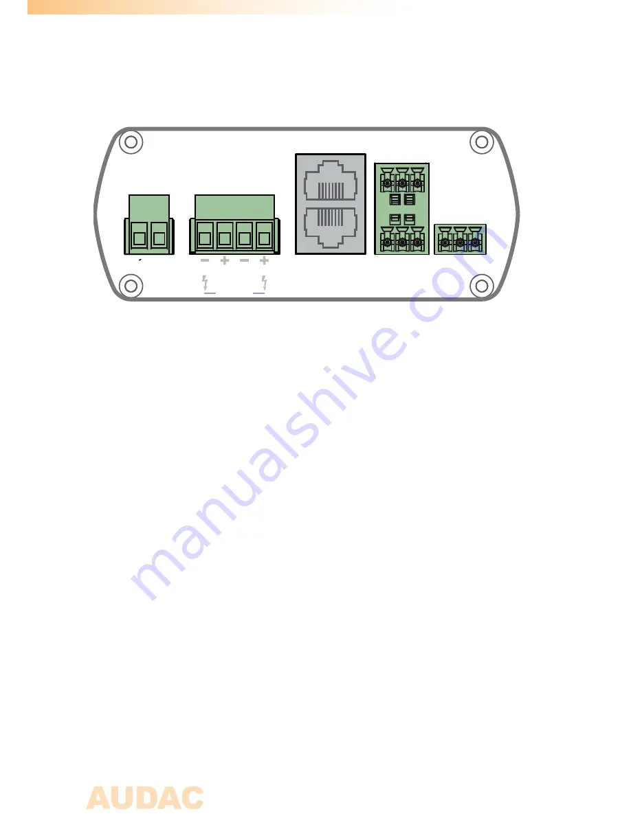
All necessary connections of the AMP20 are provided at the backside of the device. An
overview and explanation of all the connectors and possibilities is given below.
1) 24 Volts power connector:
The 24 Volts power supply connection is provided on the left side of the AMP20’s rear
panel. The included power supply (PSD241) should be connected to the terminal block
connectors. Pay attention to the polarity when connecting the power supply.
2) Loudspeaker output:
The loudspeakers should be connected to the 4-pins ‘AMP OUT’ Terminal Block
connector. Depending on the position of the Stereo and Mono / Bridge switch on
the front panel, the corresponding audio output will be available here. When used
in Stereo mode, the left loudspeaker(s) should be connected to the two leftmost
terminals and the right loudspeaker(s) should be connected to the two rightmost
terminals. When used in Bridge mode, the loudspeaker(s) should be connected to the
two outer terminals.
3) Remote wall mixer and Volume controller connections:
Two RJ45 connectors are provided for connecting Remote wall mixers and external
overall volume controllers. The connections on these extension ports should be made
by using a simple CAT5 twisted pair (or better) cable in a straight pinout configuration.
The pinout and colour coding is described on Chapter 1 of this instruction manual.
The remote wall mixer connection carries the supply voltage to the wall input unit and
a stereo differential audio signal from the wall input unit to the amplifier.
Rear panel
GND
L+
L-
GND
R+
R-
REMOTE WALL
MIXER
VOLUME
CONTROLLER
GND
+
-
AMP OUT
POWER
GND +24V
BRIDGE
LEFT
RIGHT
MI
C
LINE
GND
Содержание AMP20
Страница 1: ...AMP20 User Manual www audac eu ...
Страница 2: ...2 ...
Страница 4: ...4 ...
Страница 8: ...8 ...
Страница 18: ...18 Notes ...
Страница 19: ...19 Notes ...
Страница 20: ...20 Notes ...


