Auber Instruments
v1.2
6/12/2019
1
KIT-CUBE2S Installation Guide
1.
Enclosure
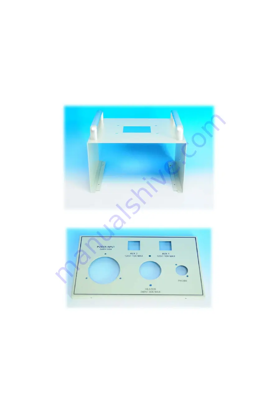
Disassembling all the screws and the enclosure will be spitted into four pieces:
Figure 1. Top and Body of Qbox1.
Figure 2. Rear Plate of Qbox1.
Страница 1: ...struments v1 2 6 12 2019 1 KIT CUBE2S Installation Guide 1 Enclosure Disassembling all the screws and the enclosure will be spitted into four pieces Figure 1 Top and Body of Qbox1 Figure 2 Rear Plate...
Страница 2: ...o the space inside the enclosure is limited we recommend you to start with the installation of heat sink SSR fuse holders and mini relays first and then complete the wiring for the parts During all th...
Страница 3: ...12 2019 3 2 Heat Sink and Solid State Relay SSR There are 4 M6 screws offered to mount the heat sink on the top of CUBE box Figure 5 Top view of heat sink installation Figure 6 Bottom view of heat sin...
Страница 4: ...er Instruments v1 2 6 12 2019 4 Figure 7 Apply Silicon Grease uniformly before mounting the SSR Figure 8 Using 2 M4 screws provided to mount the SSR on the heat sink Apply silicon grease at this area...
Страница 5: ...re provided to mount each fuse holder in the KIT Figure 9 2 pairs of M3 screw and nuts are provided for mounting each mini relay 1 pair of M3 scew and nuts are provided for mounting each fuse holder F...
Страница 6: ...Figure 10 Outside View Screw cap should be facing outside Figure 11 Inside view all nuts should be installed inside Tips if you have rivets and rivet gun you can also use it to mount the fuse holder...
Страница 7: ...needed Connector Types QTY For Yellow Stud Ring Terminal 12 10AWG 4 Ground Red Insulated Female Disconnect Square 22 18 AWG 8 5 15R socket Mini Relay Blue Insulated Female Disconnect Square 16 14 AWG...
Страница 8: ...Auber Instruments v1 2 6 12 2019 8 Figure 14 10 AWG hot wires Figure 15 14 AWG hot wires...
Страница 9: ...s of illuminated switches Remove the unnecessary green wires by insert a pair of tweezers into the corresponding slots for green wires and pull them out gently by hand at the same time If the wires ca...
Страница 10: ...Note L6 30R heater output should be mount with the 2 M4 screws XLRCON M connector needs 2 pairs of M3 screws and nuts Figure 18 Continue with hot and neutral wires like the photo Leave the hot wires t...
Страница 11: ...Auber Instruments v1 2 6 12 2019 11 Figure 19 Start front panel from switches and EZBoil Figure 20 Add wiring harness to the switches and mount breaker bracket AUX2 AUX1 Slope...
Страница 12: ...12 Figure 21 Push the two side legs out so that it can clamp on the front panel firmly Figure 22 Wire the breaker switch before fit it into the bracket and continue the wiring for EZboil and hot L1 bu...
Страница 13: ...res between front plate with rear plate Figure 24 Place fuse into the fuse holder and jump wire for each mini relay from its pin NO to the corresponding fuse holder L14 30P Breaker Switch AUX2 Mini Re...
Страница 14: ...front plate and rear plate with enclosure body finish the SSR wiring Figure 26 Complete the wiring of mini relays and fuse holders Tips Due to the limit space inside the enclosure please do not tight...
Страница 15: ...test apply hot glue or silicon sealant for controller and the 5 15R pump outlets these parts do not come with mounting screw so they may go loose after time In the end close the enclosure by fastening...