ATX VersAtive Pro Mondo Скачать руководство пользователя страница 10

CHAPTER 2: INSTALLATION

2-2


VersAtive

®

Pro Mondo – Hardware Interface Manual

• 

The power supply power cords must include a grounding pin and must be plugged into grounded electrical outlets.

• 

Remove any jewelry or metal objects from your body, which are excellent metal conductors that can create short 

circuits and harm you if they come into contact with printed circuit boards or areas where power is present.

• 

This product may be connected to an IT power system. In all cases, make sure that the unit is also reliably connected 

to Earth (ground).

2.3.2  General Precautions

• 

The server weighs approximately 85 lbs (38.6kg) when fully loaded. When lifting the system, two people at either 

end should lift slowly with their feet spread out to distribute the weight. Always keep your back straight and lift with 

your legs.

• 

While working on the system, do not wear loose clothing such as neckties and unbuttoned shirt sleeves, which can 

come into contact with electrical circuits or be pulled into a cooling fan.

• 

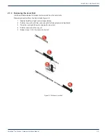
After accessing the inside of the node, close the chassis back up and secure it to the rack unit with the retention 

screws and ensure that all connections have been made.

2.3.3  Chassis Precautions

• 

Determine the placement of each component in the rack before you install the rails.

• 

Install the heaviest components on the bottom of the rack first, and then work up.

• 

Use a regulating uninterruptible power supply (UPS) to protect the server from power surges, voltage spikes and to 

keep your system operating in case of a power failure.

• 

Allow any power supply modules to cool before touching them.

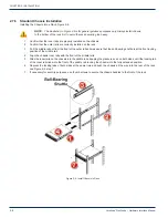
2.3.4  Rack Precautions

• 

Ensure that the leveling jacks on the bottom of the rack are fully extended to the floor with the full weight of the rack 

resting on them.

• 

In single rack installation, stabilizers should be attached to the rack. In multiple rack installations, the racks should 

be coupled together.

• 

Always make sure the rack is stable and secured before extending a Mondo chassis from the rack.

• 

You should extend only one Mondo chassis at a time - extending two or more simultaneously may cause the rack to 

become unstable.

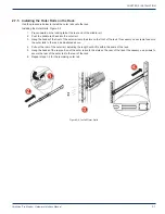
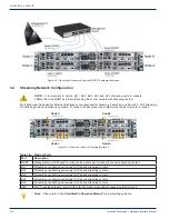
2.4  General Mechanical

• 

The equipment will require 2RU of vertical rack space and may be mounted directly above or below other equipment 

without providing space between, however, 1RU space should be maintained from other equipment which generates 

significant heat. Leave enough clearance in front of the rack to enable you to extend the Mondo Chassis completely 

(~25 inches) and approximately 30 inches of clearance in the back of the rack to allow for sufficient airflow and ease 

of servicing.

• 

Be sure to maintain freedom of air movement around equipment. Installation of the equipment in enclosed racks 

is not recommended due restricted air flow. The equipment is designed to operate to specification in an ambient 

temperature of +10°C to +35°C (+50°F to +95°F). Normal room temperature is recommended to ensure proper long 

term operation of the equipment. 

• 

Consideration should be given to the connection of the equipment to the mains power and the effect that any possible 

overloading of circuits might have on over current protection and wiring. 

• 

A reliable ground must be maintained at all times. To ensure this, the rack itself should be grounded. Particular 

attention should be given to power supply connections other than the direct connections to the branch circuit (i.e. the 

use of power strips, etc.).

• 

Rear support of the unit is mandatory and rails for attachment to rear supports are provided. Do not use the unit 

chassis to support other equipment. Alternately, if rear support rails are unavailable or impractical, install the unit on 

a well supported shelf.

Содержание VersAtive Pro Mondo

Страница 1: ...Hardware Interface Manual Patent Pending License free End of Sale as of March 31 2017 ...

Страница 2: ...t The following symbols are in use NOTE This symbol usage will call the reader s attention to an important operation feature of the equipment which may be safety related or may cause a service outage FYI This symbol indicates that there is helpful related information available in this note or elsewhere in the guide DigiVu II DigiVu DigiVu UCrypt and VersAtive Pro are registered trademarks of ATX i...

Страница 3: ...for IPMI 1 4 2 INSTALLATION 2 1 2 1 Chapter Contents 2 1 2 2 Preparation for Installation 2 1 2 3 Precautions 2 1 2 4 General Mechanical 2 2 2 5 Power Considerations 2 3 2 6 Gigabit Ethernet Ports 2 4 2 7 Installing the Chassis into a Rack 2 4 3 STARTUP 3 1 3 1 Chapter Contents 3 1 3 2 Management Computer 3 1 3 3 Connecting to Your Computer 3 1 3 4 Streaming Network Configuration 3 2 4 SAFETY 4 1 ...

Страница 4: ... GENERAL GUIDE NOTES ii VersAtive Pro Mondo Hardware Interface Manual This page intentionally left blank ...

Страница 5: ...ant to understand that the standard ATX Networks default IP address of 192 168 0 23 for the MGMT port is assigned to all nodes Before connecting each node management port MGMT ETH0 to the management switch the IP addresses must be re configured Refer to chapter STARTUP on page 3 1 for further guidance 1 3 Node Interface Panel The Mondo chassis includes four front control panels on the handles Figu...

Страница 6: ...elated to its related node This section explains what each LED indicates when illuminated Alert This LED is illuminated when an alert condition occurs A solid red light indicates an overheat condition in the system A flashing red light which flashes in one second intervals indicates a fan failure A flashing red light which flashes in four second intervals indicates a power supply failure When noti...

Страница 7: ...H4 12 ETH5 1 7 Unit Identifier Switches UID Two Unit Identifier UID Switch LED Indicators are available on each node The Front Panel UID Switch LED is located at the control panel adjacent each node see Figure 1 1 The Rear UID Switch is located next to the VGA Connector of each node see Figure 1 3 When the user presses a UID switch on the front panel or back panel both rear and front UID LED Indic...

Страница 8: ... ftp supermicro com utility IPMIView The IPMI User Guides http www supermicro com manuals other Embedded_BMC_IPMI pdf http www supermicro com manuals other SMT_IPMI_Manual pdf IPMIView Software Manual http www supermicro com manuals other IPMIView20 pdf Command Line Interface tool ftp ftp supermicro com utility SMCIPMITool SMCIPMITool_User_Guide pdf NOTE Security measures should be taken if traffi...

Страница 9: ... need to install the system into the rack Follow the steps in the order given to complete the installation process in a minimum amount of time 2 3 Precautions 2 3 1 Electrical Precautions Basic electrical safety precautions should be followed to protect yourself from harm and the VersAtivePro Mondo chassis from damage Be aware of the locations of the power on off switch on the chassis as well as t...

Страница 10: ... resting on them In single rack installation stabilizers should be attached to the rack In multiple rack installations the racks should be coupled together Always make sure the rack is stable and secured before extending a Mondo chassis from the rack You should extend only one Mondo chassis at a time extending two or more simultaneously may cause the rack to become unstable 2 4 General Mechanical ...

Страница 11: ...n North America If shipped outside of North America the unit will be supplied with an IEC cord set appropriate for the locale to which it is shipped When installing the equipment it is the responsibility of the installer to determine that sufficient capacity is available in the electrical circuit feeding the unit to avoid overloading the supply circuit Each AC powered unit will require power to be...

Страница 12: ...ection provides information on installing the Mondo chassis into a rack unit with the rails provided There are a variety of rack units on the market which may mean that the assembly procedure will differ slightly from the instructions provided You should also refer to the installation instructions that came with the rack unit you are using NOTE This rail will fit a rack between 26 5 and 36 4 deep ...

Страница 13: ...ter rails Releasing Inner Rail from the Outer Rails Figure 2 2 1 Identify the left and right outer rail assemblies 2 Pull the inner rail out of the outer rail until it is fully extended as illustrated 3 Press the locking tab down to release the inner rail 4 Pull the inner rail all the way out 5 Repeat steps 1 3 for the second outer rail Figure 2 2 Release Inner Rail ...

Страница 14: ...en correctly identified 2 Place the inner rail firmly against the side of the chassis aligning the hooks on the side of the chassis with the holes in the inner rail 3 Slide the inner rail forward toward the front of the chassis until the rail clicks into the locked position which secures the inner rail to the chassis 4 Secure the inner rail to the chassis with the screws provided 5 Repeat steps 1 ...

Страница 15: ...rail 3 Hang the hooks of the front of the outer rail onto the slots on the front of the rack If necessary use screws to secure the outer rails to the rack as illustrated above 4 Pull out the rear of the outer rail adjusting the length until it fits within the posts of the rack 5 Hang the hooks of the rear portion of the outer rail onto the slots on the rear of the rack If necessary use screws to s...

Страница 16: ... of the outer rail and make sure that the ball bearing shuttle is at the front locking position of the middle rail 4 Align the chassis inner rails with the front of the middle rails 5 Slide the inner rails on the chassis into the middle rails keeping the pressure even on both sides until the locking tab of the inner rail clicks into the front of the middle rail locking the chassis into the fully e...

Страница 17: ...treaming ports to a GbE capable switch or risk uncontrolled continuity errors as the 100 Base T network is flooded 3 1 Chapter Contents Management Computer Connecting to Your Computer Streaming Network Configuration 3 2 Management Computer It is required that the Management Computer meet these minimum requirements Wired Ethernet network port Web browser for Management GUI on 192 168 0 23 3 3 Conne...

Страница 18: ...t eth1 Streaming or publishing exclusively for IP based streaming content eth2 Streaming or publishing exclusively for IP based streaming content eth3 Streaming or publishing exclusively for IP based streaming content eth4 Streaming or publishing exclusively for IP based streaming content eth5 Streaming or publishing exclusively for IP based streaming content IPMI DHCP enabled hardware level inter...

Страница 19: ...d in the operating instructions or as marked on the device NOTE a For 115 VAC operation use the power cord supplied for operation from a 115 VAC source b For 230 VAC operation use the power cord supplied for operation from a 230 VAC source POWER CORD PROTECTION Power supply cords should be routed so that they are not likely to be pinched by items placed upon or against them paying particular atten...

Страница 20: ...CHAPTER 4 SAFETY 4 2 VersAtive Pro Mondo Hardware Interface Manual This page intentionally left blank ...

Страница 21: ...SUPPORT Tel 905 428 6068 Toll Free 800 565 7488 USA Canada only Press 3 for Technical Support Then press 1 for Digital Video Products DVIS DigiVu UCrypt VersAtivePro DigiStream Email digitalvideosupport atxnetworks com CUSTOMER SERVICE ATX Networks 1 501 Clements Road West Ajax ON L1S 7H4 Canada Tel 905 428 6068 Toll Free 800 565 7488 USA Canada only Press 1 for Customer Service Fax 905 427 1964 T...

Страница 22: ...17 ANW1110 1 501 Clements Road West Ajax ON L1S 7H4 Canada Tel 1 905 428 6068 Toll Free 1 800 565 7488 Fax 1 905 427 1964 Toll Free Fax 1 866 427 1964 www atxnetworks com support atxnetworks com End of Sale as of March 31 2017 ...

Отзывы: