ATX Maxnet II QMP200 Скачать руководство пользователя страница 7

INSTALLATION

2. Installation

2.1.  Product Inspection

 Carefully unpack the amplifier module from the shipping box. If the box or amplifier module is damaged, please notify the 

freight company to make a damage claim. If you suspect that there is a problem with the amplifier module that may affect it’s 

safe operation, do not install such a suspect Amplifier into the Active MAXNET II Chassis.

2.2.  Module Installation into the Active MAXNET

®

 II Chassis

Slide  the  dual-width  QMP200  amplifier  module  into  an  open  slot  in  the Active  MAXNET  II  Chassis,  one  that  spans  two 

single-width module locations beginning with an odd number (indicated by a white marker on the chassis), until the module 

drops into its lock position. 

The module must be inserted into an odd number slot in order for the amplifier module to 

properly mate to the active chassis back plane.

 If the module is installed properly, the amplifier will make contact with the 

24 VDC power bus in the chassis and if there is a MAXNET II Power Supply Module installed in the chassis, and it is plugged 

into the respective power source, the module’s PWR (Power) LED indicator will light green. To remove an amplifier module 

from the chassis, gently lift the front handle and pull back on the module until it is clear of the chassis guide slot.  

Initially, when inserted in the Active MAXNET II Chassis, the amplifier will start alarming (the front panel ALM (Alarm) LED 

indicator will start flashing red), as there is no RF input signal. The amplifier will stop alarming once RF signal is applied to the 

input and all other parameters are within operating conditions.

2.3.  RF Connections

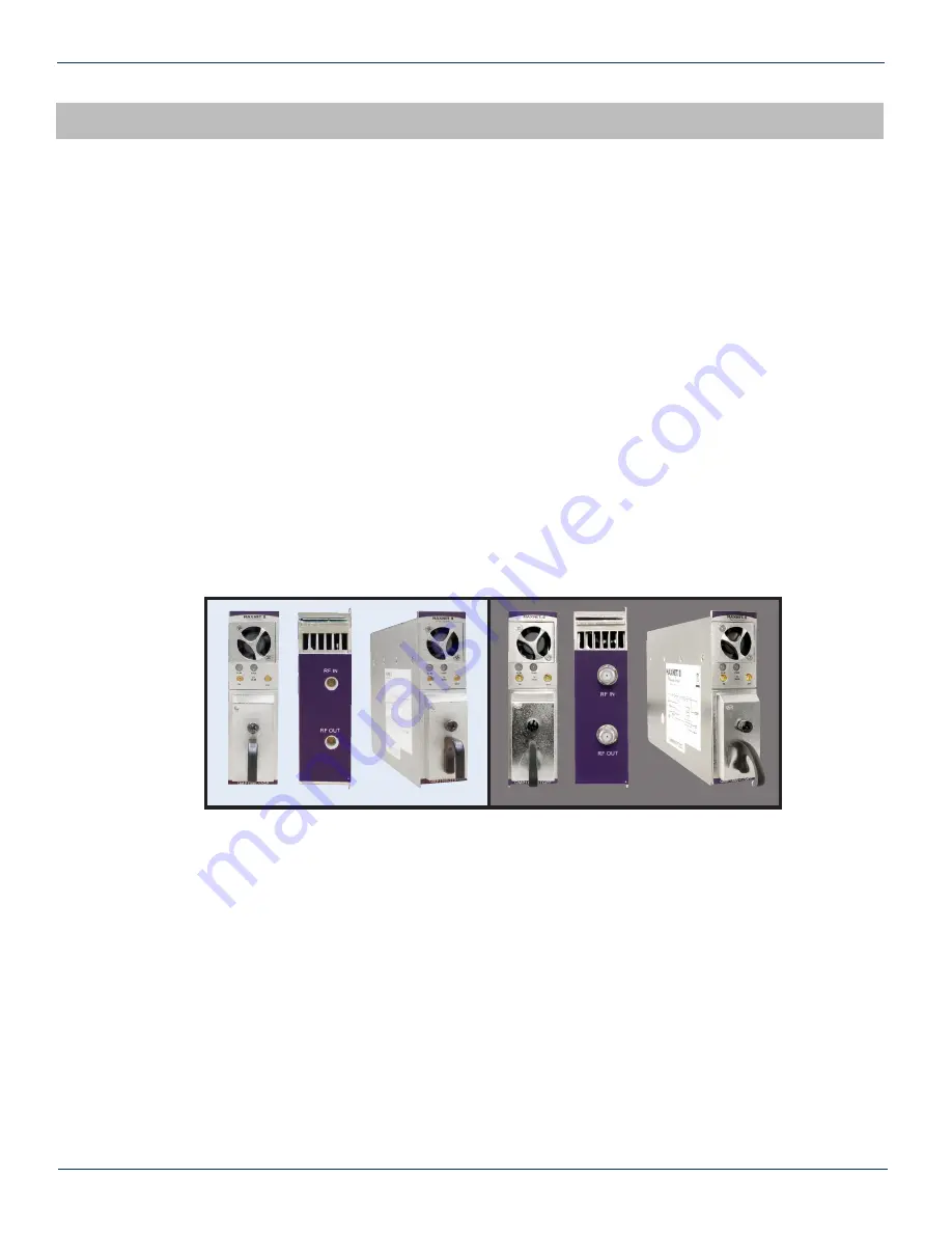
The RF jacks on the QMP200 amplifiers front/rear panel are MCX [female]. As an option, the RF jacks on the rear panel 

can be F type [female]. There will be one RF input and one RF output at the rear, plus two front panel 20 dB test points per 

QMP200 amplifier. The output (OUT) test point is –20 dB relative to the RF output. The input (IN) test point is –20 dB relative 

to the RF input, if input PAD and EQ are 0 dB (see Functional Diagram). The RF Input connector on the rear panel is the 

top connector and the RF Output connector on the rear panel is the bottom connector. Connect a test jumper from output or 

test point ports to a signal level meter or spectrum analyzer to verify signal quality and adjust RF levels before connecting 

subsequent equipment.

The operator can adjust the RF level by inserting PAD’s and EQ’s as shown in the Functional Diagram (Figure 1).

          MAXNET

®

 II – QMP200 Return RF/IF Amplifier Manual – Installation & Operation Manual 

2-1

CHAPTER 1:  PRODUCT DESCRIPTION


CHAPTER 2:  INSTALLATION

Figure #2:  Front & Rear Panel Pictures

Shown with MCX (left) and F (right) Rear Panel Connectors

Содержание Maxnet II QMP200

Страница 1: ...QMP200 Return RF IF Amplifier Installation Operation Manual CCAP Compliant 1 2 GHz ...

Страница 2: ... by one or more U S or foreign patents Other non ATX product and company names in this manual are the property of their respective companies Although every effort has been taken to ensure the accuracy of this document it may be necessary without notice to make amendments or correct omissions Specifications subject to change without notice ...

Страница 3: ...ssis Interface Options 3 1 3 2 SCTE HMS MIB Software Definition of Module 3 1 3 3 Web Interface 3 1 3 4 Updating Active Chassis Firmware 3 2 3 5 Factory Reset 3 2 4 STATUS MONITORING FEATURES 4 1 4 1 SNMP Parameters 4 1 4 2 SNMP MIBs Required 4 2 5 MAINTENANCE TROUBLESHOOTING 5 1 5 1 Maintenance 5 1 5 2 Troubleshooting 5 1 6 SERVICE SUPPORT 6 1 6 1 Contact ATX Networks 6 1 6 2 Warranty Information...

Страница 4: ... 2 3 LED Status Indications 2 2 4 Plug in PAD Specifications 2 3 5 Plug in 1 GHz EQ Specifications 2 3 6 Plug in 1 218 GHz EQ Specifications 2 3 7 Plug in PAD EQ Ordering Information 2 3 8 Common Module SNMP Parameters 4 1 9 QMP200 SNMP Parameters 4 1 10 General SCTE HMS MIBs Required 4 2 11 QMP200 SCTE HMS MIBs Required 4 2 ii MAXNET II QMP200 Return RF IF Amplifier Manual Installation Operation ...

Страница 5: ...ality including high density packaging through the use of MCX coaxial cable connectors in conjunction with Mini RG 59 Type coaxial cable Also featured are front access alarm LED indicator 20 dB test points and the capability of module status monitoring through SNMP based Managers The MAXNET II SNMP interface is HMS compliant Please refer to the web page for up to date specifications www atxnetwork...

Страница 6: ...al Specifications 1 2 MAXNET II QMP200 Return RF IF Amplifier Manual Installation Operation Manual CHAPTER 1 PRODUCT DESCRIPTION RF DETECTOR 24 VDC PWR CHASSIS COMM RF OUTPUT RF INPUT 20 dB OUTPUT TEST POINT 20 dB INPUT TEST POINT ALARM FAN ACTIVE FUSE POWER FAN CTRL MONITOR CONTROL PAD EQ PAD EQ Return RF IF Amplifier ...

Страница 7: ... module until it is clear of the chassis guide slot Initially when inserted in the Active MAXNET II Chassis the amplifier will start alarming the front panel ALM Alarm LED indicator will start flashing red as there is no RF input signal The amplifier will stop alarming once RF signal is applied to the input and all other parameters are within operating conditions 2 3 RF Connections The RF jacks on...

Страница 8: ... and plug in equalizer are accessible by removing the front cover Remove the access cover from the front of the QMP200 Amplifier module by turning the thumbscrew counter clockwise This will expose two blocks of two PAD s EQ s The ones on the left side are connected to the RF Input and the ones on the right side are connected to the RF Output __________________________________________________ 1 If ...

Страница 9: ...le 6 Plug in 1 218 GHz EQ Specifications Table 7 Plug in PAD EQ Ordering Information Part Number Description MP PAD Plug in Pad 1218 MHz dB value 0 20 dB must order in quantities of 10 MP EQ Plug in EQ 1000 MHz dB value 1 5 10 5 dB must order in quantities of 10 MP EQLH Plug in EQ 1218 MHz dB value 1 5 10 5 dB must order in quantities of 10 MPPT Pad EQ Insertion and Extraction Tool ...

Страница 10: ...2 4 MAXNET II QMP200 Return RF IF Amplifier Manual Installation Operation Manual CHAPTER 2 INSTALLATION This page left intentionally blank ...

Страница 11: ...Bs Management Information Bases are freely downloadable from the SCTE www scte org standards ATX was able to support all modules using the SCTE standard HMS MIBs so no custom MIBs are required 3 2 SCTE HMS MIB Software Definition of Module The headend RF Amp MIB is used to provide only an Output RF detector value allowing HI and LO alarm thresholds to be set 3 3 Web Interface The MAXNET II chassis...

Страница 12: ...conds then disconnect the network cable and proceed to the next chassis Leave the recently updated chassis powered until it completes a reboot j Optionally the chassis may now be factory reset to restore all IP settings to factory defaults Read the factory reset section fully before doing this to know what data will be lost when doing this 3 5 Factory Reset A factory reset will restore the chassis...

Страница 13: ...number or purchase order for tracking entPhysicalAssetID Serial No Module s serial number entPhysicalSerialNum Hardware Rev Hardware rev of module entPhysicalHardwareRev Firmware Rev Firmware rev of module entPhysicalFirmwareRev Temperature C Module s current heatsink temperature heCommonTemperature Alarm Detection Control detectionEnabled normal operation with active alarms detectionDisabled used...

Страница 14: ...CTE ROOT 028 36 SCTE HMS ROOTS 072 37 SCTE HMS HEADENDIDENT MIB 114 38 11 SCTE HMS HE COMMON MIB 111 84 1 SCTE HMS PROPERTY MIB 026 38 1 SCTE HMS HE FAN MIB 117 84 3 SCTE HMS HE POWER SUPPLY MIB 116 84 2 HMS SCTE SCTE HMS HE RF MIB 133 83 4 SCTE HMS HE RF AMP MIB 131 94 1 Table 10 General SCTE HMS MIBs Required Table 11 QMP200 SCTE HMS MIB s Required ...

Страница 15: ...al for the round LED near the RJ45 port at the rear of the chassis to be solid ON or OFF during various states of system boot up If the chassis has been powered up solid green on the round 24V LED near the terminal block at the rear of the chassis for at least 2 minutes then the yellow LED should be blinking to indicate the chassis software is running If it is not a reboot is necessary If the chas...

Страница 16: ...V green LED on the rear of the chassis If it is off then the problem is that the chassis is not getting power See MPAC MPDC troubleshooting section If it is on or if other modules in the chassis are okay the module itself is suspect Continue Remove the suspect module and trade slot positions with another functioning module a If the suspect module is okay and the previously good module fails contac...

Страница 17: ...le fan is operating If not replace with a new fan from ATX Fan Part MPFANA using the below procedure 5 Install replacement fan in the opposite order shown Ensuring that a The red and black wires are aligned b The labelled side of the fan faces inward toward the module c The wires do not bunch up behind the fan interfering with fan rotation MAXNET II QMP200 Return RF IF Amplifier Manual Installatio...

Страница 18: ...5 4 MAXNET II QMP200 Return RF IF Amplifier Manual Installation Operation Manual CHAPTER 5 MAINTENANCE TROUBLESHOOTING This page left intentionally blank ...

Страница 19: ...rs manufacturer s defects or failures 6 3 Safety IMPORTANT FOR YOUR PROTECTION PLEASE READ THE FOLLOWING WATER AND MOISTURE Care should be taken so that objects do not fall and liquids are not spilled into the enclosure through openings POWER SOURCES The device should be connected to a power supply only of the type described in the operating instructions or as marked on the device GROUNDING OR POL...

Страница 20: ...n Canada Rev 07 15 ANW0782 1 501 Clements Road West Ajax ON L1S 7H4 Canada Tel 1 905 428 6068 Toll Free 1 800 565 7488 Fax 1 905 427 1964 Toll Free Fax 1 866 427 1964 www atxnetworks com support atxnetworks com ...

Отзывы: