Page 44
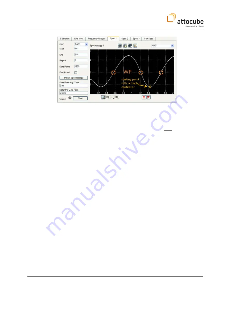
Figure 18:
Working point WP.
The fiber-tip cavity now must be adjusted to a minimum (ADC1
min
) of the
interferogram by tuning the DC voltage of the dither piezo (normally on
DAC1). Hence, as soon as the sample starts pushing against the tip the
cavity will decrease and the interferometric signal must increase.
2. Starting the auto approach:
The auto approach settings must be set accordingly, i.e. the voltage of the
limiter must be set slightly higher than the minimum of the interferometric
signal and the stop condition must be set to “ > threshold”. Remember that
the autoapproach monitors the parameter set kin the feedback window. This
parameter must be set to the DC signal of the photo-detector (ADC1).
Examples for correct autoapproach settings are given in the 3 figures below.
The auto approach will stop when the tip touches the sample. The cantilever
will be bent and the interference signal will sharply increase, see figure to
the left
Содержание attoAFM I
Страница 20: ...Page 20 III 5 Changing the AFM Cantilever...


