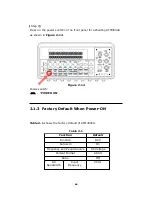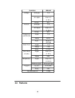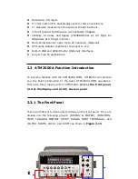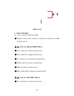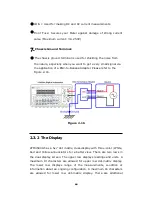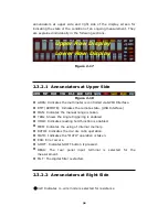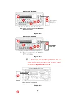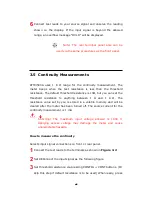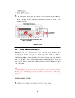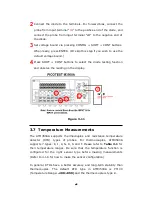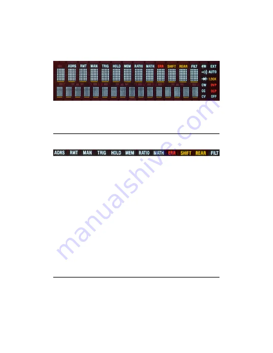
annunciators at upper side and right side of the display screen for
indicating the state or the condition of an ongoing measurement. They
are explained individually in the following sections.
Figure 2-17
2.3.2.1 Annunciators at Upper Side
Figure 2-18
ADRS: Indicates the multimeter is controlled via GPIB Interface.
RMT (REMOTE): Indicates the remote state. (USB Interface)
MAN: Indicates the manual range is taken.
TRIG: Shows the single triggering is enabled.
HOLD: Indicates reading hold function is enabled.
MEM: Indicates the using of internal memory.
RATIO: Indicates the dcv:dcv ratio operation.
MATH: Indicates the “MATH” operation is taken.
ERR: Error occurs.
SHIFT: Indicates SHIFT button is pressed.
REAR: The rear panel input terminal is selected for the
measurement.
FILT: The digital filter is started.
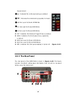
2.3.2.2 Annunciators at Right Side
4W: Indicates 4 –wire mode is selected for resistance
30
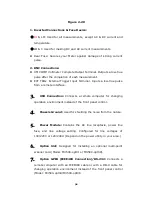
Upper Row Display
Lower Row Display
Содержание ATM3500A
Страница 1: ...ATTEN EU ATM3500A 6 5 Digit Digital Multimeter...
Страница 2: ...User s Manual ATM3500A DMM User s Manual 2 Printed date 11 2011 Version 1 05...
Страница 50: ...Figure 3 18 50 5...
Страница 120: ...668 Manual Calibration Version Error 669 Self Test Version Error 670 Command Version Error 120...


