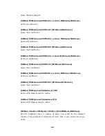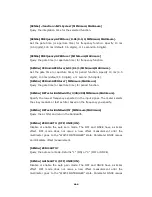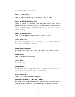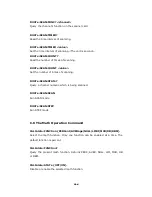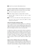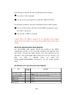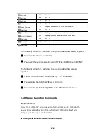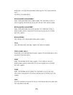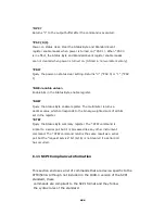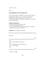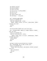
Enable the bus controller’s IEEE-488 SRQ interrupt.
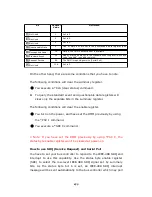
Procedures to Determine When a Command Sequence is Completed.
Clear the DMM’s output buffer by sending a device clear message.
Clear the event registers by using *CLS command.
Enable “operation complete” by using the *ESE 1 command.
Send the *OPC? command and enter the result to enable
synchronization.
When bit 5 is set in the status byte summary register, please use a
serial poll to check. Then you could set the DMM for an SRQ
interrupt by using *SRE 32.
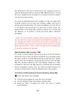
Usage of the Messages Available Bit (MAV)
You can use the status byte “message available bit 4” to decide when
data is available to read in the bus controller. When the first reading
trigger occurs by using the command TRIGger:SOURce:IMMediate, the
DMM will automatically enable the bit 4. The DMM will clear bit 4 only
after entire messages have been read from the output buffer.
The MAV bit can indicate only when the first reading is generated by
the READ? command. So this will be helpful for you as a trigger event
such as BUS or EXTernal will occur. In addition, the MAV bit is set only
after all specified measurements have completed by using the INITiate
and FETCH? commands. That means in detail, the INITIate command
is used to store readings in the DMM’s internal memory. And the
FETCH? command is used to transfer readings to the DMM’s output
buffer.
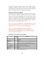
Signal by Using *OPC When Data is in the Output Buffer
Normally, to use the “operation complete bit 0” in the standard event
register will signal as a command sequence is completed. The bit is set
in the register after executing an *OPC command. And if you send an
*OPC after a command loading a message in the DMM’s output buffer,
175
Содержание ATM3500A
Страница 1: ...ATTEN EU ATM3500A 6 5 Digit Digital Multimeter...
Страница 2: ...User s Manual ATM3500A DMM User s Manual 2 Printed date 11 2011 Version 1 05...
Страница 50: ...Figure 3 18 50 5...
Страница 120: ...668 Manual Calibration Version Error 669 Self Test Version Error 670 Command Version Error 120...

