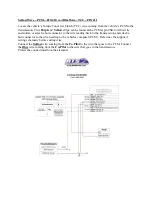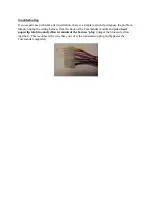
heading into the wire loom to the vehicle’s computer (PCM). Reference the supplied wiring
schematic before cutting wire.
Connect the
Yellow
wire coming from the
Co-Pilot
to the wire that goes to the PCM. Connect
the
Blue
wire coming from the
Co-Pilot
to the wire that goes to the transmission.
Protect the connections from the elements.
Green Wire- Vehicle Speed Sensor (VSS) – PIN #17
Locate the VSS (Vehicle Speed Sensor) wire. This
Gray w/ Black
stripe wire can be found at
the transmission connector (passenger side of the transmission, above the pan rail). Tap by
soldering the Green Co-Pilot wire to the VSS wire and protect from elements. A poor VSS
connection is the most common wiring problem.
If at any time you would like to bypass the Co-Pilot’s operation, simply unplug the wiring
harness from the Co-Pilot Module and jumper the harness’ blue and yellow terminals
together with a paperclip.
Wiring The Co-Pilot For 1994.5-1997 models
-
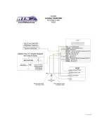
The Co-Pilot has several connections that need to be made in order for it to function properly.
There are several wires which are optional but still included to give the Co-Pilot a more versatile
use depending on your trucks current setup. Use the diagram below as a reference when
installing your Co-Pilot to avoid any conflicts or confusion.
Содержание Co-Pilot
Страница 11: ......


