


4.7 ON/OFF Input Signals (pin C1...C4 referred to DGND pin B4)
Analog Drivers Compatibility -
default
for series 12 or higher
The four ON/OFF digital input signals (DI) can be used to activate compatibility functionalities with E-BM-AC and E-ME-AC analog drivers
(see section
). If digital inputs are not connected, the driver behavior corresponds to an E-BM-AS series 11 or lower
or
Internal Reference Generation - software selectable
When the driver is configured in internal reference generation mode (see 7.6), the 4 ON/OFF input signals (DI) are used to select the active
reference signal, among the available stored values. If the 4 ON/OFF input signals (DI) are not active, the driver can be commanded by
external analog reference. The polarity of the digital inputs can be customized: active status = 24 V
DC
is the default setting.
Note:
for /P option DI3 and DI4 are not available
4.8 Possible combined options:
/12W
,
/12PW
,
/12CIW
,
/AW
,
/ACIW
,
/APW
,
/CIW
,
/PW
only for 05H
/12I
,
/12P
,
/AI
,
/AP
for 01H and 05H
5
E-A-PS-USB/DB9
USB to serial adapter
E-C-PS-DB9/RJ45
serial
cable
The software is available in different versions according to the driver’s options (see table
GS500
):
E-SW-BASIC
support: NP (USB) PS (Serial) IR (Infrared)
E-SW-FIELDBUS
support: BC (CANopen) BP (PROFIBUS DP) EH (EtherCAT)
EW (POWERLINK) EI (EtherNet/IP) EP (PROFINET)
E-SW-*/PQ
support: valves with SP, SF, SL alternated control (e.g. E-SW-BASIC/PQ)
WARNING:
drivers RS232 port is not isolated!
6
VALVE SETTINGS AND PROGRAMMING TOOLS
Free programming software, web download:
E-SW-BASIC
web download = software can be downloaded upon web registration at www.atos.com ; service and DVD not included
Upon web registration user receive via email the Activation Code (software free license) and login data to access Atos
Download Area
DVD programming software, to be ordered separately:
E-SW-*/PQ
DVD first supply = software has to be activated via web registration at www.atos.com ; 1 year service included
Upon web registration user receive via email the Activation Code (software license) and login data to access Atos
Download Area
E-SW-*-N/PQ
DVD next supplies = only for supplies after the first; service not included, web registration not allowed
Software has to be activated with Activation Code received upon first supply web registration
Atos Download Area:
direct access to latest releases of E-SW software, manuals, USB drivers and fieldbus configuration files at www.atos.com
USB Adapters, Cables and Terminators, can be ordered separately
Valve's functional parameters and configurations, can be easily set and optimized using Atos E-SW
programming software connected via RS232 serial port to the digital driver (see table
FS900
).
For fieldbus versions, the software permits valve's parameterization through USB port also if the driver
is connected to the central machine unit via fieldbus.
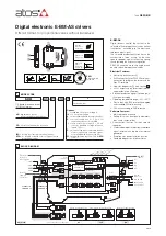
Connection
G030
E-BM-AS digital inputs (DI1..DI4) activate compatibility functionalities with E-BM-AC and E-ME-AC analog drivers:
5
ANALOG DRIVERS COMPATIBILITY
- only for E-BM-AS series 12 or higher
REFERENCE COMPATIBILITY
Digital Inputs Signals
Digital driver
Analog driver
24 V
DC
to DI1:
0 V
DC
to DI1:
DI1
24 V
DC
E-BM-AS 01H
E-BM-AS 05H
E-BM-AC 01F
E-BM-AC 05F
E-BM-AC 011F
E-ME-AC 01F
E-ME-AC 05F
01H
Voltage 0 ÷ 5 V
DC
/ 0 ÷ 100%
Current 4 ÷ 20 mA / 0 ÷ 100%
05H
Voltage ± 5 V
DC
/ ± 100%
Current 4 ÷ 20 mA / 0 ÷ 100%
See section 4.2
DI2
0 V
DC
DI3
0 V
DC
DI4
0 V
DC
Note:
set 0 V
DC
to DI1 and power-off/on the driver to restore latest settings
REFERENCE INVERSION
Digital Inputs Signals
Digital driver
Analog driver
24 V
DC
to DI2:
0 V
DC
to DI2:
DI1
24 V
DC
E-BM-AS 05H
E-BM-AC 05F
Voltage 0 ÷ 5 V
DC
/ 0 ÷ -100%
Current 4 ÷ 20 mA / 0 ÷ -100%
Voltage 0 ÷ 5 V
DC
/ 0 ÷ 100%
Current 4 ÷ 20 mA / 0 ÷ 100%
DI2
24 V
DC
DI3
0 V
DC
DI4
0 V
DC
Note:
to enable reference inversion, set 24 V
DC
to DI1 before driver power-on
RAMP SWITCH OFF
Digital Inputs Signals
Digital driver
Analog driver
24 V
DC
to DI3:
0 V
DC
to DI3:
DI1
24 V
DC
E-BM-AS 01H
E-BM-AS 05H
E-ME-AC 01F
E-ME-AC 05F
Ramp excluded
Ramp activated
DI2
0 V
DC
DI3
24 V
DC
DI4
0 V
DC
Notes:
to enable ramp switch off, set 24 V
DC
to DI1 before driver power-on; DI3 not available for /P option
011F CONFIGURATION
Digital inputs dignals
Digital driver
Analog driver
24 V
DC
to DI4:
0 V
DC
to DI4:
DI1
(*)
E-BM-AS 05H
E-BM-AC 011F
Driver configuration 011F
(*) = don’t care
Driver configuration 05H
(*) = don’t care
DI2
(*)
DI3
(*)
DI4
24 V
DC
Notes:
set 0 V
DC
to DI4 and power-off/on the driver to restore latest settings; DI4 not available for /P option