


C3 / +5 V
B1 / CMD1
C3 / +5 V
B1 / CMD1
B3 / CMD2
C3 / +5 V
B1 / CMD1
C4 / -5 V
10 K
Ω
10 K
Ω
10 K
Ω
10 K
Ω
B2 / CMD-
B2 / CMD-
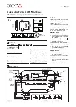
1 single solenoid valve
4.1 Power supply
The power supply must be appropriately stabilized or rectified and filtered: apply at least a 10000
μ
F/40 V capacitance to single phase
rectifiers or a 4700
μ
F/40 V capacitance to three phase rectifiers.
4
POWER SUPPLY AND SIGNALS SPECIFICATIONS
3
MAIN CHARACTERISTICS
Power supply (see 4.1)
Standard
Nominal: +24 V
DC
Rectified and filtered: V
RMS
= 20 ÷ 32 V
MAX
(ripple max 10 % V
PP
)
option /12
Nominal: +12 V
DC
Rectified and filtered: V
RMS
= 10 ÷ 14 V
MAX
(ripple max 10 % V
PP
)
Max power consumption
50 W 01H single solenoid valve and 05H double solenoid valve
100 W 05H two single solenoid valves
Current supplied to solenoids
I
MAX
= 2.7 A with +24 V
DC
power supply for standard proportional valves (3,2
Ω
solenoid)
I
MAX
= 3.3 A with +12 V
DC
power supply for proportional valves with /6 option (2,1
Ω
solenoid)
I
MAX
= 2.5 A with +24 V
DC
power supply for ex-proof proportional valves (3,2
Ω
solenoid) for
/A option
Analog input signal (see 4.2)
Voltage: range ±10 V
DC
Input impedance: Ri > 50 k
Ω
Current: range ±20 mA
Input impedance: Ri = 500
Ω
Enable and optical insulated ON/OFF
inputs (see 4.5, 4.7)
Range : 0 ÷ 24 V
DC
( OFF state: 0 ÷ 5 V
DC
; ON state: 9 ÷ 24 V
DC
)
Input impedance: Ri > 10 k
Ω
Output supply (see 4.4)
±5 V
DC
@ max 10 mA : output supply for external potentiometers (only for
/P option
)
Status output (see 4.6)
Output range : 0 ÷ 24 V
DC
( ON state > [power supply - 2 V] ; OFF state < 1 V ) @ max 1,4 A
Alarms
Solenoid not connected, short circuit and cable break with current reference signal
Format
Plastic box ; IP20 protection degree ; L 35 - H 7,5 mm rail mounting as per EN60715
Operating temperature
-20 ÷ +60 °C
(-20 ÷ +40 °C for 05H version if drive two single solenoid proportional valves; storage -25 ÷ +85 °C)
Mass
130 g
Additional characteristics
Short circuit protection of current output to solenoids; protection against reverse polarity of power supply
Compliance
CE according to EMC directive 2014/30/EU (Immunity: EN 61000-6-2; Emission: EN 61000-6-4)
RoHS Directive 2011/65/EU as last update by 2015/65/EU
REACH Regulation (EC) n°1907/2006
Communication interface
RS232 serial connection (not insulated), Atos protocol with ASCII coding (see section
)
9
Recommended wiring cable
LiYCY shielded cables: 0,5 mm
2
for length up to 40 m [1,5 mm
2
for power supply and solenoids]
Max conductor size (see section
)
12
2,5 mm
2
2 single solenoid valves
1 double solenoid valve
01H
05H
05H
A safety fuse is required in series to each power supply: 2,5 A time lag fuse for 01H single solenoid valve and 05H double solenoid valve
5 A time lag fuse for 05H two single solenoid valves
4.2 Reference Input Signals (pin B1 and B3, both referred to pin B2)
The driver proportionally transforms the external reference input signal into the current supplied to the solenoid.
The driver is designed to receive one (01H) or two (05H) analog reference inputs (CMD1 on pin B1, CMD2 on pin B3); both signals are refer-
red to a common electric ground (CMD- on pin B2). CMD1 has to be used in case of 05H version that drives one double solenoid valve.
CMD2 has to be used in case of 05H version that drives two single solenoid valves or transducer input for /W option (see 4.3).
The input range is software selectable among voltage (0 ÷ ±10 V
DC
) or current (4 ÷ 20 mA with cable break detection or 0 ÷ ±20 mA).
Defaults for standard: 0 ÷ 10 V
DC
for two position valves; 0 ÷ ±10 V
DC
for three position valves (see valve’s tech. table).
Default for /I option: 4 ÷ 20 mA (see valve’s tech. table)
Other ranges can be set by software. Internal reference generation is software selectable (see 7.6).
Note: software selection of analog input range (voltage or current) is applied to both signals CMD1 and CMD2.
4.3 Pressure Input Signal (pin B3 referred to pin B2) only for, /W option)
When hydraulic power limitation is active (see 7.7), input signal CMD2 must be connected to an external pressure transducer installed on
the hydraulic system; maximum input range 0 ÷ 10 V
DC
.
4.4 Output supply Signal for external reference potentiometers (/P option)
The reference analog signals can be generated by one (01H) or two (05H) external potentiometers directly connected to the driver, using
the ±5 V
DC
supply output available at pin C3 and C4. Reference input signal can be set up via software to ±5 V
DC
, in order to match poten-
tiometer output signal.
Option /12
This driver execution is designed to receive a 12 V
DC
power supply and it is commonly used in mobile application.
A safety fuse is required in series to each driver power supply:
A safety fuse is required in series to each power supply: 4 A time lag fuse for 01H single solenoid valve and 05H double solenoid valve
6,3 A time lag fuse for 05H two single solenoid valves
4.5 Enable Input Signal (pin D3 referred to pin D2)
Enable input signal allows to enable/disable the current supply to the solenoids, without removing the electrical power supply to the driver;
it is used to maintain active the serial connection and the other driver functions when the valve must be disabled for safety reasons.
To enable the driver, supply a 24V
DC
on pin D3 referred to pin D2.
4.6 Status Output Signal (pin D4 referred to pin D2)
Status output signal indicates fault conditions of the driver (short circuits, solenoids not connected, cable broken for 4 ÷ 20mA input)
and is not affected by Enable input signal status: fault presence corresponds to 0 V
DC
, normal working corresponds to 24 V
DC
.
When hydraulic power limitation function is active (see 7.7), status output signal can be software configured to indicate power limitation status:
not active (0 V
DC
) or active (24 V
DC
).