

Industrial Managed Gigabit Ethernet Switch
EMG8508 / EMG8510 Series
EMG8608 / EMG8610 Series
Version 0.1
Updated in June, 2016
P/N:89900497G
Inside the package you will find the following items:
■ Industrial Managed Gigabit Ethernet Switch x 1
■ Protective caps for all SFP ports (Depend on purchased model)
■ Installation Guide with Warranty Card x 1
Never install or work on electrical or cabling during periods of lightning activity.
Never connect or disconnect power when hazardous gases are present.
Warning:Hot Surface Do Not Touch.
Caution: CLASS 1 LASER PRODUCT. Do not stare into the laser!
EMG8508 / EMG8510 Series
EMG8608 / EMG8610 Series
BI_DC-
BI_DC+
BI_DA+ / Tx+ / V+
BI_DA- / Tx- / V+
BI_DD-
BI_DD+
BI_DB- / Rx- / V-
BI_DB+ / Rx+ / V-
P1
RUN
1
5
9
P2
ALM
2
6
Ring
3
7
R.M.
4
8
10
2
3
1
4
5
RxD
GND
N.C.
TxD
N.C.
2
3
1
4
5
Relay2
N.C.
Relay2
Relay1
Relay1
2
3
1
F.G.
V+
V
-
N.C.
Console
Relay
P1
P2
1
2
3
4
8
5
6
7
1
2
3
4
5
6
7
8
9
10
11
12
13
14
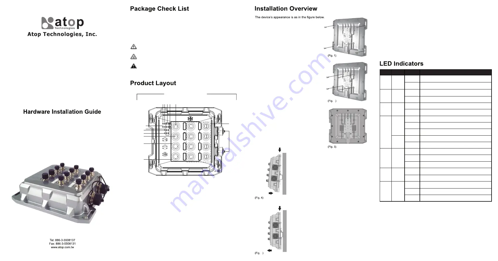
1. M12 A-Coding Console Port
2. SFP Ports LEDs (for EMG8510 Series)
3. M12 X-coding Ethernet ports and/or PoE LEDs
4. RUN LED
5. PWR1 LED
6. PWR2 LED
7. ALM LED
8. Ring LED
9. Ring Master LED
10. M12 A-Coding Alarm relay or alarm output
11. M12 S-Coding PWR1 connector
12. M12 S-Coding PWR2 connector
13. 1000 BASE-X SFP Slots (for EMG8510 Series)
14. 10/100/1000 BASE-T(X) M12 X-coding Ethernet ports and/or
10/100/1000 BASE-T(X) PoE M12 X-coding Ethernet Ports
(EMG8508-4PoE/ EMG8510-4PoE-2SFP, PoE ports at Port 1,2,5,6)
5
2
You can then choose whether to plug in the other
peripheral ports at this point or do it later depending
on the actual location of the device or level of
comfort for performing such operation.
Remeber to plug in the protective caps for the
unused SFP.
4.
If you have purchased the DIN-Rail kit, Once the
plate has been firmly put in place, proceed to mount
the whole device as shown in (Fig. 4).Proceed to
(Fig. 5) if you want to remove the device from
DIN-Rail.
5.
Next we can then proceed to connect the device to
the LAN (switch or PC, depending on the case), take
care on using the M12 connector; after this we can
then proceed to the device’s settings
6.
Proceed to place the screws on the back
of the device as show in (Fig. 1).
1.
If you have the VESA kit, proceed to place
the screws on the back of the device as
show in (Fig. 2)
2.
3.
Although internal grounding has been
done inside, in order to ensure overall
maximum performance and protect your
device, it is still strongly advised to ground
the device properly; hazardous ESD can
come into contact and damage your
equipment. On the power terminal block,
there is a terminal for Frame Ground, you
can choose whether to connect it to the
grounding or you may opt to connect to
the grounding screw next to the terminal
block ( the one chosen should be connect-
ed at all times ) (Fig. 3)
1
2
1
2
Message
■ The housing has a good thermal conductivity material, so the heat can be
dissipated to the outside through the housing by conduction-convection .
■ This switch’s factory IP by default is 10.0.50.1 you can access the device by its
Web UI once it is connected to a physical network (or using Management Utility,
for more information on Management Utility, please refer to its manual). Please
be aware that the PC needed for this procedure needs to be in the same
subnet, or you may refer yourself to the device User’s Manual.
*Management Utility only support user name, password and IP address change.
Detail setting please set on Web UI.
Color
Status
Name
Message
P1
P2
Alarm
RUN
LAN
Ring
R.M
SFP
Green
Red
Green
Green
Amber
Green
Green
Green
On
Off
On
Off
Blinking
Off
On
Blinking
Off
On
Off
On
Blinking
Off
On
Off
On
Blinking
Off
Power is supplied from PWR1/PWR2
No power input detected from PWR1/PWR2
Alarm is triggered by user defined events
Alarm is not triggered by user defined events
AP firmware is running normally
System is not ready or halt
Ethernet is linked
Ethernet is active and data is being transmitted
Ethernet is not linked
Power is being supplied to a Powered Device (PD)
Power is not supplied to a PD
Ring is enabled
Ring is connected successfully
Ring is disabled
The device is a Master of the ERPS or IA-Ring
The device is a Slave of the ERPS or IA-Ring
Port is linked
Data is transmitting on this port
No data is transmitting
If the device requires servicing of any kind, you may need to disconnect and
remove it from its mounting. The initial installation should be done in a way that
makes this as convenient as possible.
■ Voltage/Power lines should be properly insulated as well as other cables. Be
careful when handing the so as to not trip over
■ Do not under any circumstance open the device for any reason. Please
contact your dealer for any repair needed or follow the instructions on section
of your User’s Manual.
Field Maintenance and Service