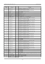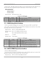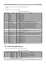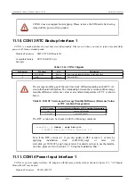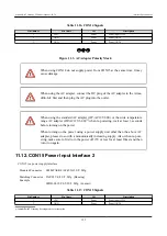
Pin Num-
ber
Pin Name
I/O
Description
59
CON2_USB_HS_DP
In/Out
CON2_USB plus side signal, connected to i.MX7 Dual USB HSIC controller via USB
HUB controller (port 1)
60
CON2_USB_HS_DM
In/Out
CON2_USB minus side signal, connected to i.MX7 Dual USB HSIC controller via USB
HUB controller (port 1)
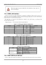
There are a number of add-on modules available which can be connected.
There are many signals which connect to both CON1 and CON2. Please be careful
of possible signal conflicts when designing an expansion board.
11.4. CON4 SD Interface
CON 4 is an SD interface compatible with UHS-I (SDR104, maximum clock frequency: 196.36MHz). The SD signal
lines are connected to the SD/MMC controller (uSDHC1) on the i.MX7 Dual.
The power (SD_VDD) supplied to the SD card can be controlled with the SD1_RESET_B pin of the i.MX7 Dual. Power
is supplied during high level output and power is turned off with low level output.
Mounted Connector
DM1B-DSF-PEJ(82)/HIROSE ELECTRIC
Table 11.5. CON4 Signals
Pin Number
Pin Name
I/O
Description
1
SD_DAT3
In/Out
SD data bus (bit 3), connected to SD1_DATA3 pin of i.MX7 Dual
2
SD_CMD
In/Out
SD command / response, connected to SD1_CMD pin of i.MX7 Dual
3
GND
Power
Power (GND)
4
SD_VDD
Power
Power (SD_VDD)
5
CLK
Out
SD clock, connected to SD1_CLK pin of i.MX7 Dual
6
GND
Power
Power (GND)
7
SD_DAT0
In/Out
SD data bus (bit 0), connected to SD1_DATA0 pin of i.MX7 Dual
8
SD_DAT1
In/Out
SD data bus (bit 1), connected to SD1_DATA1 pin of i.MX7 Dual
9
SD_DAT2
In/Out
SD data bus (bit 2), connected to SD1_DATA2 pin of i.MX7 Dual
Table 11.6. CON4 Card Detection and Write Protect Detection
Item
Description
Card detection
Connected to SD1_CD_B pin of i.MX7 Dual
(Low: card inserted, High: card removed)
Write protect detection
Connected to SD1_WP pin of i.MX7 Dual
(Low: write enabled, High: write disabled)
Armadillo-IoT Gateway G3Product Manual - INTL
Interface Specifications
117


