background image

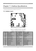
The is no guarantee that the parts installed have the part numbers shown in Ta-
ble 11.2, “Armadillo-IoT Interface List (Side B)”. Please check the parts specifi-
cations and change history table which can be downloaded from the Atmark Techno
Users' site for the parts on your product.

11.2. CON1 Add-on Interface 1

CON1 is an expansion interface. It connects to signal lines of the i.MX7 Dual which offer multiple functions (multi-

plexing), and functions such as USB, UART, SPI, I2C, SD, CAN, PWM and GPIO can be interfaced to.

Mounted Connector

DF17(4.0)-60DS-0.5V(57)/HIROSE ELECTRIC

Matching Connector
Example

DF17(4.0)-60DP-0.5V(57)/HIROSE ELECTRIC

Allowable Current

0.3A (per one terminal)

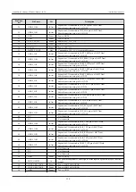
Table 11.3. CON1 Signals

Pin Num-

ber

Pin Name

I/O

Description

1

GND

Power

Power (GND)

2

GND

Power

Power (GND)

3

GPIO3_IO0

In/Out

Expansion I/O, connected to LCD_CLK pin of i.MX7 Dual

Shared connection with pin 41 of CON2

4

GPIO3_IO1

In/Out

Expansion I/O, connected to LCD_ENABLE pin of i.MX7 Dual

Shared connection with pin 40 of CON2

5

GPIO3_IO2

In/Out

Expansion I/O, connected to LCD_HSYNC pin of i.MX7 Dual

Shared connection with pin 39 of CON2

6

GPIO3_IO3

In/Out

Expansion I/O, connected to LCD_VSYNC pin of i.MX7 Dual

Shared connection with pin 38 of CON2

7

GPIO4_IO2

In/Out

Expansion I/O, connected to UART2_RXD pin of i.MX7 Dual

Shared connection with pin 32 of CON2

8

GPIO4_IO3

In/Out

Expansion I/O, connected to UART2_TXD pin of i.MX7 Dual

Shared connection with pin 34 of CON2

9

GPIO4_IO4

In/Out

Expansion I/O, connected to UART3_RXD pin of i.MX7 Dual

Shared connection with pin 36 of CON2

10

GPIO4_IO5

In/Out

Expansion I/O, connected to UART3_TXD pin of i.MX7 Dual

Shared connection with pin 37 of CON2

11

GPIO4_IO6

In/Out

Expansion I/O, connected to UART3_RTS pin of i.MX7 Dual

Shared connection with pin 35 of CON2

12

GPIO4_IO7

In/Out

Expansion I/O, connected to UART3_CTS pin of i.MX7 Dual

Shared connection with pin 50 of CON2

13

GPIO4_IO10

In/Out

Expansion I/O, connected to I2C2_SCL pin of i.MX7 Dual

Shared connection with pin 24 of CON2

14

GPIO4_IO11

In/Out

Expansion I/O, connected to I2C2_SDA pin of i.MX7 Dual

Shared connection with pin 25 of CON2

15

GPIO5_IO11

In/Out

Expansion I/O, connected to SD2_RESET_B pin of i.MX7 Dual

Shared connection with pin 33 of CON2

16

GPIO6_IO19

In/Out

Expansion I/O, connected to SAI2_TXFS pin of i.MX7 Dual

Shared connection with pin 46 of CON2

17

GPIO6_IO20

In/Out

Expansion I/O, connected to SAI2_TXC pin of i.MX7 Dual

Shared connection with pin 47 of CON2

Armadillo-IoT Gateway G3Product Manual - INTL

Interface Specifications

113

Содержание Armadillo-IoT Gateway G3

Страница 1: ...Armadillo IoT Gateway G3 Product Manual INTL AGX3150 Version 1 0 0 2018 02 19 Atmark Techno Inc http www atmark techno com Armadillo Official Site http armadillo atmark techno com ...

Страница 2: ...Armadillo IoT Gateway G3Product Manual INTL Atmark Techno Inc Copyright 2016 2018 Atmark Techno Inc Version 1 0 0 2018 02 19 ...

Страница 3: ...ing the Command Line Terminal GNOME Terminal 26 3 2 4 Using Serial Communication Software minicom 27 3 3 Interface Layout 28 3 4 Connections 29 3 5 Slide Switch Configuration 31 3 6 Using the vi Editor 31 3 6 1 Starting vi 31 3 6 2 Character Input 32 3 6 3 Moving the Cursor 32 3 6 4 Deleting Characters 33 3 6 5 Saving and Quitting 33 4 Startup and Shutdown 34 4 1 Startup 34 4 2 Login 46 4 3 Managi...

Страница 4: ...oot Modes 88 6 2 Bootloader Functions 88 6 2 1 How to Specify the Linux Kernel Image and Device Tree Blob 88 6 2 2 Specifying the Root File System 89 6 2 3 Saving Environment Variables 90 6 2 4 Linux Kernel Boot Options 90 7 Build Procedure 92 7 1 Building the Bootloader 92 7 2 Building the Linux Kernel 93 7 3 Building a Debian GNU Linux Root File System 94 7 3 1 Creating the Factory Default Root ...

Страница 5: ...10 WWAN Expansion Interface 119 11 9 CON11 MicroSIM Interface 120 11 10 CON13 RTC Backup Interface 1 121 11 11 CON14 Power Input Interface 1 121 11 12 CON15 Power Input Interface 2 122 11 13 CON16 Power Output Interface 123 11 14 CON17 3G Antenna Interface 123 11 15 CON20 WLAN Interface 123 11 16 CON22 RTC Backup Interface 2 125 11 17 JP1 Boot Device Setting Jumper 126 11 18 SW1 to SW3 User Switch...

Страница 6: ...odifications 54 5 11 List of Devices 55 5 12 Connecting Devices 55 5 13 Disconnecting Devices 55 5 14 Creating a Wired LAN Interface eth0 Connection 56 5 15 Ping Confirmation of Wired LAN 56 5 16 Connecting to a Wireless LAN Access Point 56 5 17 Creating a Wireless LAN wlan0 Connection 57 5 18 Ping Confirmation of Wireless LAN 58 5 19 microSIM 59 5 20 Installing MicroSIM 59 5 21 Creating a 3G Conn...

Страница 7: ... Changing the Digital Output State 86 5 57 Getting the Digital Input State 86 5 58 Calculation Formula of Input Voltage to the AD Converter 87 5 59 Obtaining the Input Voltage to the AD Converter 87 6 1 Displaying U Boot Command Help 88 6 2 Booting from a Linux Kernel Image Stored on Partition 1 of eMMC 89 6 3 Specifying the Root File System Stored in Partition 2 of eMMC 89 6 4 Restoring All Envir...

Страница 8: ...faces and TTY Device Files 80 5 13 Add on Interfaces and TTY Device Files 80 5 14 RS485 Setting and Default Values 81 5 15 Setting RS485 from Linux kernel Boot Options 82 5 16 Add on Interfaces and TTY Device Files 82 5 17 Add on Interfaces and TTY Device Files 84 5 18 RS485 Setting and Default Values 84 5 19 Setting RS485 from Linux kernel Boot Options 85 5 20 Add on Interfaces and GPIO Class Dir...

Страница 9: ...11 10 CON7 Signals 119 11 11 CON9 Signals 119 11 12 CON10 Signals 120 11 13 CON11 Signals 120 11 14 CON13 Signals 121 11 15 RTC Versions and Average Monthly Difference Reference Value at 25 C Ambient Temperature 121 11 16 CON14 Signals 122 11 17 CON15 Signals 122 11 18 CON16 Signals 123 11 19 CON20 Signals 124 11 20 CON22 Signals 125 11 21 RTC Versions and Average Monthly Difference Reference Valu...

Страница 10: ...ghly read and fully understood the product manuals and related materials the technical information offered on our web site and related device data sheets Also please carry out full tests beforehand in order to provide and maintain reliability and safety This product is not intended for uses that require extremely high reliability and safety in terms of functionality and accuracy such as medical eq...

Страница 11: ... conditions while also making sure it is done in an environment with anti static measures established like using anti static mats anti static measures for workers such as conductive shoes and human body earthing and countermeasures against dis charges from equipment Also when storing this product avoid using plastic bags and containers that are prone to static electricity and store them in conduct...

Страница 12: ...are Usage Precautions About Software Contained in this Product The source code of the Linux compatible software preinstalled in the default shipping state of this product is provided as open source unless otherwise indi vidually specified including written electronic data or oral notification For redistribution and so on please do so at your own risk according to the license notice included in eac...

Страница 13: ...correctly in ac cordance with the instruction manual In order to comply with the technical standards of VCCI it is necessary to supply power from the DC jack CON14 with an AC adapter The add on modules have not been subjected to the VCCI compliance check test as single modules It has been confirmed that they meet VCCI technical standards when connected to Armadillo IoT Please use the add on module...

Страница 14: ...gy may not be used for the purpose of development of weapons of mass destruction for the purpose of military use or other military related uses or in devices which have had their production use sale or procurement prohibited by national or overseas law or regulations 1 8 Trademarks Armadillo is a registered trademark of Atmark Techno Inc All other company names product names and related trademarks...

Страница 15: ...preparing a development PC and installing required tools 2 1 2 What is Armadillo IoT Gateway The Armadillo IoT Gateway is a platform for easily and quickly developing gateways for IoT M2M and is based on the proven Armadillo embedded platform It combines a high degree of flexibility ease of development and robustness as an embedded device in a well balanced manner and is suitable for those who wan...

Страница 16: ...llo IoT RN4020 Add on Module BT00 OP AGA BT00 00 Armadillo IoT EnOcean Add on Module EN00 a OP AGA EN00 00 Armadillo IoT Wi SUN Add on Module WS00 OP AGA WS00 00 Armadillo IoT Isolated Digital I O Analog Input Add on Module DA00 OP AGA DA00 00 a Scheduled to be released 2 3 Specifications The main specifications of Armadillo IoT Gateway G3 are as follows Table 2 2 Specifications Product Number AGX...

Страница 17: ...ing flange a Size for SLC use SLC is set at the factory b 3G mobile communication MicroSIM card sold separately c Batteries are not included d Two add on modules can be equipped e Power consumption is measured when LAN USB and serial connectors are connected to external equipment Consumption of externally connected equipment is not included f Power consumption varies depending on the radio wave en...

Страница 18: ...ial Connector Used to connect the included USB serial converter 7 MicroSIM Slot Used to connect a MicroSIM card 8 User LED1 A green LED which users can freely assign functions to 9 User LED2 10 User LED3 11 User LED4 12 WWAN LED Green LED that indicates the communication status of the 3G module 13 User Switch 1 A tact switch which users can freely assign functions to 14 User Switch 2 15 User Switc...

Страница 19: ...loader image is located in the QSPI Flash memory but it can also be placed on the SD card Linux Kernel A Linux kernel in the uImage format can be used In the factory default state the Linux kernel image is located in the eMMC but it can also be placed on the SD card by using bootloader functionality 1 For the dotted line blocks whether they are mounted or not depends on the product model For the m...

Страница 20: ...dress Size Description 0x00000000 0x001003FF Approx 1MByte U Boot bootloader image 0x00100400 0x001403FF 256 KBytes License information 0x00140400 0x007FFFFF Approx 6 7 MBytes Reserved area The memory map of Armadillo IoT s eMMC is shown below Table 2 6 eMMC Memory Map When Using Installation Disk v20160928 or Later Partition Size Description 1 32 MBytes Linux kernel image Device tree blob 2 Appro...

Страница 21: ...ational Checks A VMware virtual machine data image is provided to allow easier software development and operational checks of Atmark Techno products The VMware virtual machine data image is referred to as ATDE Atmark Techno Development Envi ronment To start ATDEm VMware virtualization software is used The ATDE image data is compressed in the tar xz format Please extract it with the tools suitable ...

Страница 22: ...rocessor requirements of the guest operating system The documentation can be obtained from the VMware web site http www vmware com 3 2 1 2 Obtaining the ATDE6 Archive The ATDE6 archive can be obtained from the Armadillo site http armadillo atmark techno com or the development set DVD The version of ATDE6 supporting this product is v20160321 or later ATDE6 may not work properly depending on the ope...

Страница 23: ...uded in the development set 2 Starting 7 Zip Start 7 Zip 3 Selecting the xz Compressed File Extract the xz compressed file into a file in the tar format Select the tar xz file and click Extract 4 Specifying the xz Compressed File Extraction Destination Specify where to extract the file to and click OK Armadillo IoT Gateway G3Product Manual INTL Before Turning on Armadillo 23 ...

Страница 24: ...le with the same procedure as used for the tar archive file Select the tar format file click Extract specify the Extracted location and click OK 7 Confirming Completion of the Extraction When extraction of the tar archive file is finished the extraction of the ATDE6 archive is complete The ATDE6 data image is output to the folder specified with Extracted location Armadillo IoT Gateway G3Product Ma...

Страница 25: ...s008 vmdk atde6 i386 vmxf atde6 i386 s004 vmdk atde6 i386 s009 vmdk 3 2 1 4 Starting ATDE6 ATDE6 can be started by opening the virtual machine configuration vmx file in the directory where you extracted the ATDE6 archive Users which can be used to log on to ATDE6 are shown in Table 3 1 Usernames and Passwords 3 Table 3 1 Usernames and Passwords Username Password Permissions atmark atmark General u...

Страница 26: ...nnected to the guest operating system Table 3 2 Removable Devices Used for Operational Checks Device Device Name USB serial converter Future Devices FT232R USB UART Work PC physical serial port Serial port 3 2 3 Starting the Command Line Terminal GNOME Terminal In ATDE6 we start a command line terminal that provides a CUI Character based User Interface environment Various commands to be run on ATD...

Страница 27: ...ation Baud rate 115 200bps Data Length 8 bit Stop Bit 1 bit Parity None Flow Control None To start minicom configuration please do as shown in Figure 3 3 Configuring minicom After configuration is com pleted save it to the default setting dfl and exit PC LANG C minicom setup Figure 3 3 Configuring minicom To start minicom please do as shown inFigure 3 4 Starting minicom PC LANG C minicom wrap devi...

Страница 28: ...board connector 60 pin 0 5mm pitch Connection cycles 40 times a CON2 Add on Interface 2 Board to board connector 60 pin 0 5mm pitch Connection cycles 40 times a CON4 SD Interface SD slot CON6 LAN Interface RJ 45 Connector CON7 USB Host Interface Type A connector CON9 Debug Serial Interface Pin header 7 pin 1 25mm pitch Connection cycles 40 times a CON10 WWAN Expansion Interface Board to board conn...

Страница 29: ... 2 54mm pitch SW1 User Switch 1 Tact switch SW2 User Switch 2 Tact switch SW3 User Switch 3 Tact switch SW4 Reset Switch Tact switch LED1 WWAN LED LED green surface mounted LED2 User LED2 LED green surface mounted LED3 User LED1 LED green surface mounted LED4 User LED3 LED green surface mounted LED5 User LED4 LED green surface mounted a The connection life cycle count is a guideline at the time of...

Страница 30: ...Card MicroSIM card Figure 3 7 Armadillo IoT Gateway Connection Example When using the AC adapter connect the DC plug of the AC adapter to the Arma dillo IoT first and then plug the AC plug into the outlet 4 Armadillo IoT Gateway development set accessories Armadillo IoT Gateway G3Product Manual INTL Before Turning on Armadillo 30 ...

Страница 31: ...Unlike the text editors such as gedit and emacs installed in ATDE a major feature of the vi editor is that it has operating modes It has a command mode and an input mode All characters entered in command mode are treated as commands In input mode characters can be entered as text Although the command examples shown in this chapter are written to be executed in ATDE they can be executed on Armadill...

Страница 32: ...tem Mozc Turning the Japanese input system on and off can be done with half width full width key The starting position of character input when the i and a commands are entered is shown in Figure 3 10 Explanation of Commands for Switching to Input Mode Figure 3 10 Explanation of Commands for Switching to Input Mode Delete Characters in vi Depending on the environment of the console characters may n...

Страница 33: ... Characters Figure 3 11 Explanation of Commands for Deleting Characters 3 6 5 Saving and Quitting The commands for saving the file and quitting are shown inTable 3 8 Commands for Saving and Quitting Table 3 8 Commands for Saving and Quitting Command Operation q Quit without saving changes w file Save with the filename specified in file wq Save by overwriting the file and then quit Commands for sav...

Страница 34: ...UZE300 deviceid 0x30 revid 0x11 Board Type Armadillo IoT G3 0a000000 Revison 0002 S N 2000 DRAM 00001d05 XTAL 00 Net FEC0 Figure 4 1 Log Messages Immediately After Power On To boot the Linux system enter the boot command as shown below When the command is executed the bootloader starts the Linux system and the Linux boot log is displayed in the serial communication software boot mmc1 part 0 is cur...

Страница 35: ...0 896 kB vmalloc 0xa0800000 0xff000000 1512 MB lowmem 0x80000000 0xa0000000 512 MB pkmap 0x7fe00000 0x80000000 2 MB modules 0x7f000000 0x7fe00000 14 MB text 0x80008000 0x80f1af20 15436 kB init 0x80f1b000 0x81196040 2541 kB data 0x81198000 0x81216360 505 kB bss 0x8121636c 0x81284724 441 kB SLUB HWalign 64 Order 0 3 MinObjects 0 CPUs 2 Nodes 1 Preemptible hierarchical RCU implementation RCU restrict...

Страница 36: ...l driver imx7d pinctrl 30330000 iomuxc Invalid fsl pins property in node soc aips bus 30000000 iomuxc 30330000 imx7d sdb uart1grp imx7d pinctrl 30330000 iomuxc Invalid fsl pins property in node soc aips bus 30000000 iomuxc 30330000 imx7d sdb uart2grp imx7d pinctrl 30330000 iomuxc Invalid fsl pins property in node soc aips bus 30000000 iomuxc 30330000 imx7d sdb ecspi1grp imx7d pinctrl 30330000 iomu...

Страница 37: ...egistered udp transport module RPC Registered tcp transport module RPC Registered tcp NFSv4 1 backchannel transport module imx rpmsg driver is registered Bus freq driver module loaded futex hash table entries 512 order 3 32768 bytes VFS Disk quotas dquot_6 5 2 Dquot cache hash table entries 1024 order 0 4096 bytes squashfs version 4 0 2009 01 31 Phillip Lougher NFS Registering the id_resolver key ...

Страница 38: ...cd USB 2 0 Enhanced Host Controller EHCI Driver ehci pci EHCI PCI platform driver ehci mxc Freescale On Chip EHCI Host driver usbcore registered new interface driver cdc_acm cdc_acm USB Abstract Control Model driver for USB modems and ISDN adapters usbcore registered new interface driver cdc_wdm usbcore registered new interface driver usb storage usbcore registered new interface driver usbserial u...

Страница 39: ... protocol handler initialized IR JVC protocol handler initialized IR Sony protocol handler initialized IR RC5 streamzap protocol handler initialized IR SANYO protocol handler initialized IR MCE Keyboard mouse protocol handler initialized usbcore registered new interface driver uvcvideo USB Video Class driver 1 1 1 i2c core driver mag3110 using legacy suspend method i2c core driver mag3110 using le...

Страница 40: ...d coresight etm3x 3007c000 etm ETM initialized coresight etm3x 3007d000 etm ETM initialized usbcore registered new interface driver snd usb audio NET Registered protocol family 26 nf_conntrack version 0 5 0 7812 buckets 31248 max ipip IPv4 over IPv4 tunneling driver gre GRE over IPv4 demultiplexor driver ip_gre GRE over IPv4 tunneling driver ip_tables C 2000 2006 Netfilter Core Team TCP cubic regi...

Страница 41: ...found usb 2 1 3 new full speed USB device number 3 using ci_hdrc Warning unable to open an initial console Freeing unused kernel memory 2540K 80f1b000 81196000 systemd udevd 160 starting version 215 random systemd udevd urandom read with 27 bits of entropy available usb 2 1 3 string descriptor 0 read error 22 usb 2 1 3 USB disconnect device number 3 EXT4 fs mmcblk2p2 mounted filesystem with ordere...

Страница 42: ...ocket systemd 1 Listening on Delayed Shutdown Socket systemd 1 Starting Journal Socket dev log OK Listening on Journal Socket dev log systemd 1 Listening on Journal Socket dev log systemd 1 Starting udev Control Socket OK Listening on udecdc_acm 2 1 2 1 0 ttyACM0 USB ACM device v Control Socket cdc_acm 2 1 2 1 2 ttyACM1 USB ACM device systemd 1 Listening on udev Control Socket systemd 1 Starting u...

Страница 43: ...nd Kernel File Systems OK Started udev Coldplug all Devices systemd 1 Started udev Coldplug all Devices systemd 1 Starting Various fixups to make systemd work better on Debian Starting Various fixups to make systemd work better on Debian systemd 1 Starting Load Save Random Seed Starting Load Save Random Seed systemd 1 Starting udev Kernel Device Manager Starting udev Kernel Device Manager systemd ...

Страница 44: ...ll Switch Status of rfkill0 OK Started Load Save RF Kill Switch Status of rfkill1 OK Started Copy rules generated while the root was ro systemd journald 270 Received request to flush runtime journal from PID 1 OK Started Trigger Flushing of Journal to Persistent Storage OK Started Update UTMP about System Boot Shutdown OK Started LSB Raise network interfaces OK Reached target Network OK Reached ta...

Страница 45: ...herne 00 irq 1 IPv6 ADDRCONF NETDEV_UP eth0 link is not ready IPv6 ADDRCONF NETDEV_UP wlan0 link is not ready Starting WPA supplicant OK Started WPA supplicant OK Started LSB exim Mail Transport Agent OK Reached target Multi User System OK Reached target Graphical Interface Starting Update UTMP about System Runlevel Changes OK Started Update UTMP about System Runlevel Changes Debian GNU Linux 8 ar...

Страница 46: ...d armadillo passwd Enter new UNIX password Enter new password here Retype new UNIX password Re enter armadillo With Armadillo IoT G3 being a device that can be connected to a network the security risk will be extremely high if used with the default password It is strongly recommended to change the password to one with high security strength and then manage the password appropriately thereafter 4 3...

Страница 47: ...rmission to use sudo to the guest user as an example For details on how to use vi please refer to Section 3 6 Using the vi Editor armadillo visudo User privilege specification root ALL ALL ALL ALL guest ALL ALL ALL ALL Add this line 4 Deleting a User Here we delete the guest user as an example armadillo userdel guest To delete the home directory at the same time use the r option armadillo userdel ...

Страница 48: ...ped Lighttpd Daemon OK Stopped Authenticate and Authorize Users to Run Privileged Tasks OK Stopped Getty on tty1 OK Stopped Serial Getty on ttymxc4 OK Stopped WPA supplicant OK Stopped User Manager for UID 0 OK Unmounted opt license OK Stopped LSB exim Mail Transport Agent OK Stopped target Network is Online Stopping Login Service OK Removed slice user 0 slice OK Removed slice system serial x2dget...

Страница 49: ... Stopping Create Static Device Nodes in dev OK Stopped Create Static Device Nodes in dev Stopping Remount Root and Kernel File Systems OK Stopped Remount Root and Kernel File Systems OK Reached target Shutdown systemd shutdown 1 Sending SIGTERM to remaining processes systemd journald 267 Received SIGTERM from PID 1 systemd shutdow systemd shutdown 1 Sending SIGKILL to remaining processes systemd s...

Страница 50: ...while data is being written to storage may result in the file system or the data being damaged Be sure to unmount storage first before disconnecting the power supply Armadillo IoT Gateway G3Product Manual INTL Startup and Shutdown 50 ...

Страница 51: ...ike as with other standard Linux systems By default NetworkManager automatically ups eth0 Ethernet and obtains network configuration with DHCP NetworkManager manages all network settings as connections Connections describe How to connect to the network and How to create the network and are saved in etc NetworkManager system connections Also while it is possible to save multiple connections for eac...

Страница 52: ...ing command armadillo nmcli connection up ID Figure 5 3 Enabling a Connection To disable a connection run the following command armadillo nmcli connection down ID Figure 5 4 Disabling a Connection 5 2 3 3 Creating a Connection To create a connection run the following command armadillo nmcli connection add con name ID type type ifname interface name Figure 5 5 Creating a Connection Enter the connec...

Страница 53: ...s When wireless LAN or 3G configuration is edited with the nmcli connection modify command the passphrase information is reset When making the edits please also set a passphrase at the same time For details on how to set a passphrase for wireless LAN see Section 5 2 5 Wireless LAN For setting a passphrase for 3G refer to Section 5 2 6 4 3 Notes on Altering 3G Connection Settings Please consult a n...

Страница 54: ...ration As like with ipv4 addresses a set property can be deleted by adding to the beginning of the property name Conversely a property can be added by spec ifying 5 2 3 5 3 Specifying a DNS Server An example of specifying a DNS server is shown in Figure 5 9 Specifying a DNS Server armadillo nmcli connection modify ID ipv4 dns 192 0 2 10 Figure 5 9 Specifying a DNS Server 5 2 3 6 Applying Connectio...

Страница 55: ...re 5 12 Connecting Devices To connect a device a valid connection for the device is required If the message Error neither a valid connection nor device given is displayed check if a valid connection exists by for example using the nmcli connection command 5 2 3 9 Disconnecting Devices To disconnect a device run the following command armadillo nmcli device disconnect ifname Figure 5 13 Disconnectin...

Страница 56: ...work communication In order to ensure that the wired LAN connection is used for the confirmation disable the other connections in advance 5 2 5 Wireless LAN This section explains how to use the wireless LAN module installed on Armadillo IoT As an example connect to a WPA2 PSK AES access point For details on how to connect to access points other than WPA2 PSK AES please refer to man nm settings In ...

Страница 57: ...aid 1 wlan0 associated cfg80211 Calling CRDA to update world regulatory domain cfg80211 World regulatory domain updated cfg80211 DFS Master region unset cfg80211 start_freq end_freq bandwidth max_antenna_gain max_eirp cfg80211 2402000 KHz 2472000 KHz 40000 KHz N A 2000 mBm cfg80211 2457000 KHz 2482000 KHz 40000 KHz N A 2000 mBm cfg80211 2474000 KHz 2494000 KHz 20000 KHz N A 2000 mBm cfg80211 51700...

Страница 58: ...G with another network device on the same network In the following example it is assumed that the network device has an IP address of 192 0 2 20 armadillo ping 192 0 2 20 Figure 5 18 Ping Confirmation of Wireless LAN If any connections other than wireless LAN are enabled the wireless LAN may not be used for network communication In order to ensure that the wireless LAN con nection is used for the ...

Страница 59: ...croSIM slot If this product is broken by using cards in this way it will not be covered by warranty even within the warranty period Insert the microSIM UIM card with its notch facing the direction opposite to that of insertion and with the marked side facing up Figure 5 19 microSIM Figure 5 20 Installing MicroSIM The following information is necessary to configure the APN APN Armadillo IoT Gateway...

Страница 60: ...ing immediately after creating the 3G connection or changing its settings execute the command shown in Figure 5 22 3G Data Connection armadillo nmcli connection up gsm ttyACM3 Connection successfully activated D Bus active path org freedesktop NetworkManager ActiveConnection 5 Figure 5 22 3G Data Connection 5 2 6 4 Confirming a 3G Connection Confirm that it is possible to communicate properly over...

Страница 61: ...number 5 cu Got hangup signal Disconnected armadillo usb 2 1 2 new high speed USB device number 6 using ci_hd rc cdc_acm 2 1 2 1 0 ttyACM0 USB ACM device cdc_acm 2 1 2 1 2 ttyACM1 USB ACM device cdc_acm 2 1 2 1 4 ttyACM2 USB ACM device cdc_acm 2 1 2 1 6 ttyACM3 USB ACM device cdc_acm 2 1 2 1 11 ttyACM4 USB ACM device cdc_acm 2 1 2 1 13 ttyACM5 USB ACM device Run the AT command 3 Start NetworkManag...

Страница 62: ... debian jessie armhf_aiotg3l_20170419 tar gz or later 5 2 6 5 1 Service Specifications When a MicroSIM is inserted and a valid NetworkManager 3G connection has been configured it monitors the state of the connection once every 120 seconds If the connection is disabled it is judged to be in a disconnected state and the connection is enabled If the connection is enabled a PING is executed to a speci...

Страница 63: ...ices such as 3G modules and manages their connection status By using the mmcli command line tool of ModemManager it is possible to acquire the 3G communication signal strength and SIM card information telephone number IMEI etc Please refer to man mmcli for usage details of mmcli 5 2 6 6 1 Obtaining a List of Recognized Modems To obtain a list of recognized modems run the following command armadill...

Страница 64: ...rmation a MicroSIM must be inserted Please make sure a MicroSIM is correctly inserted 5 2 6 6 3 Obtaining MicroSIM Information To obtain MicroSIM information run the following command armadillo mmcli m 0 abbreviated SIM path org freedesktop ModemManager1 SIM number number is used in the next command abbreviated armadillo mmcli i number SIM org freedesktop ModemManager1 SIM 0 Properties imsi XXXXXX...

Страница 65: ...XXXXX roaming allowed IP type none user XXXX password XXXX number 99 Rm protocol unknown IPv4 configuration method ppp address unknown prefix 0 gateway unknown DNS none IPv6 configuration method unknown Figure 5 32 Obtaining Communication Line Information 5 2 7 Configuration Example with NetworkManager The following introduces a configuration example with NetworkManager based on Figure 5 33 Networ...

Страница 66: ...10 0 24 Server eth0 192 168 10 2 192 168 10 0 24 Access Point eth0 172 16 0 1 172 16 0 0 16 a Automatically acquired with DHCP b The network device of the 3G Module 5 2 7 1 Network Configuration Procedure The network setup procedure when configuring the network shown in Figure 5 33 Network Structure Diagram is as follows Note that the created connection is saved in etc NetworkManager system connec...

Страница 67: ...is connecting A connection using the device is being enabled Disable it by referring to Figure 5 4 Disabling a Connection connected A connection using the device is enabled Disable it by referring to Figure 5 4 Disabling a Connection 2 Configure the wireless LAN wlan0 armadillo nmcli connection add type wifi ifname wlan0 ssid essid armadillo nmcli connection modify wifi wlan0 ipv4 never default ye...

Страница 68: ...face eth0 connection In order to apply the changes first disable the wired LAN eth0 connection Enable the wired LAN eth0 connection 4 Configure 3G ttyACM3 armadillo nmcli connection add type gsm ifname ttyACM3 apn apn user user password password Create the 3G ttyACM3 connection 5 Make sure that the state of eth0 ttyACM3 ppp0 and wlan0 is connected armadillo nmcli device DEVICE TYPE STATE CONNECTIO...

Страница 69: ...armadillo iptables list Figure 5 34 iptables 5 2 9 Network Applications The following explains about the network applications that can be used in the factory default image It is assumed that the network configuration of ATDE and Armadillo is the default state If the network configuration has been modified please adjust for that as nee ded 5 2 9 1 HTTP Server An HTTP server is active on Armadillo W...

Страница 70: ...3 1 Using Storage The following explains how to use storage by using an SDHC card as an example SD SDHC SDXC cards are referred to as SD cards wherever the operations can be applied to any of them When using an SDXC microSDXC card it is necessary to format it in advance by referring to Section 5 3 2 Changing and Formatting Storage Partitions This is because the Linux kernel cannot handle the exFAT...

Страница 71: ...chased have one partition and are formatted with the FAT32 file system If you want to change the partition configuration use the fdisk command An example of using the fdisk command to divide the partition of an SD card configured with just that one partition into two partitions is shown in Figure 5 39 Altering Partitions with the fdisk Command After deleting the existing partition two new primary ...

Страница 72: ...mmand To format a storage device with the FAT32 file system use the mkfs vfat command Likewise for EXT3 use the mkfs ext3 command and for EXT4 use the mkfs ext 4 command The command example for formatting partition one of the SD card with the EXT4 file system is shown below armadillo mkfs ext4 dev mmcblk0p1 Figure 5 40 Creating a EXT4 File System 5 4 LED As the Armadillo IoT s LEDs are connected t...

Страница 73: ... brightness file under the LED class directory Valid values to write to brightness are between 0 and 255 Writing a value other than 0 to brightness turns the LED on armadillo echo 1 sys class leds LED brightness Figure 5 42 Turning on an LED Since the LEDs on Armadillo IoT do not have brightness control functionality only two states 0 off and 1 255 on can be specified Writing 0 to brightness turns...

Страница 74: ...ys class leds LED delay_off Figure 5 45 Specifying timer for the LED Trigger The current trigger of the LED can be obtained by reading the trigger file The value enclosed in is the current trigger armadillo cat sys class leds LED trigger none rc feedback nand disk mmc0 mmc2 timer oneshot heartbeat backlight gpio de fault on rfkill0 phy0rx phy0tx phy0assoc phy0radio phy0tpt rfkill1 Figure 5 46 Disp...

Страница 75: ...ck has been set correctly Figure 5 47 Setting System Clock If there is a time server on the network to which Armadillo IoT is connected the system clock can be set using the NTP Network Time Protocol client armadillo ntpdate NTP SERVER 2 Jun 12 34 56 ntpdate 742 adjust time server x x x x offset 0 004883 sec armadillo date Tue Jun 2 12 34 57 JST 2015 After setting the system clock use the hwclock ...

Страница 76: ... USB device etc the index of the device file may be different 5 6 1 Confirming Events Here the evtest command is used to check the push and release events of the user switch To stop evtest enter Ctrl c armadillo evtest dev input event1 Input driver version is 1 0 1 Input device ID bus 0x19 vendor 0x1 product 0x1 version 0x100 Input device name gpio keys Supported events Event type 0 EV_SYN Event t...

Страница 77: ... the input voltage to the AD converter Since the voltage of the external battery is not divided the input voltage of the AD converter will be the voltage of the external battery as is The AD converter is implemented as an IIO Industrial I O device The input voltage can be calculated from the file under sys bus iio devices iio device0 directory The IIO device will be named iio deviceN N is a sequen...

Страница 78: ... obtaining the power supply voltage from the input voltage to the AD converter is shown below Power supply voltage mV Input voltage to AD converter x 200 24 24 Figure 5 53 Calculation Formula of the Power Supply Voltage Taking Figure 5 52 Obtaining the Input Voltage to the AD Converter as an example from the AD converter input voltage of 1 261V it can be determined that the power supply voltage is...

Страница 79: ...er supply voltage drops below 11000mV 11V armadillo vintrigger u 11000 i 30 echo 1 sys class leds led2 brightness Figure 5 55 vintrigger Command Example The vintrigger command log is output to the var log messages file armadillo cat var log messages Jul 1 09 38 52 armadillo iotg vintrigger 812 waiting for an under range alert 11000 mV Jul 1 09 38 52 armadillo iotg vintrigger 812 exceeded the limit...

Страница 80: ...o soft ware restrictions 5 10 Armadillo IoT Isolated RS232C 422 485 Add on Module RS01 The Armadillo IoT Isolated RS232C 422 485 Add on Module RS01 hereafter referred to as the isolated serial add on module has one electrically isolated RS232C RS422 RS485 serial port on it Since the device driver of the serial port of the isolated serial add on module is implemented as a TTY device it can be contr...

Страница 81: ...he logical sum of each bit Table 5 14 RS485 Setting and Default Values Configuration Description Default Value flags ENABLED bit0 0 RS485 disabled 1 RS485 enabled 1 RTS_ON_SEND bit1 0 RTS Driver Enable is low during data transmission 1 RTS Driver Enable is high during data transmission 1 RTS_AFTER_SEND bit2 0 RTS Driver Enable is low outside of data transmission 1 RTS Driver Enable is high outside...

Страница 82: ...ule WS00 The Armadillo IoT Wi SUN Add on Module WS00 hereafter referred to as Wi SUN add on module is equipped with ROHM BP35A1 The Wi SUN add on module can be controlled from the TTY device file using ASCII commands The add on interface that connects the Wi SUN add on module and the corresponding TTY device file are shown below Table 5 16 Add on Interfaces and TTY Device Files Add on Interface TT...

Страница 83: ...e armhf_aiotg3_20160705 tar gz or later root file system Use a root file system created using x1 debian builder v1 1 0 or later For other ASCII commands and detailed information on BP35A1 please refer to ROHM documentation ROHM Sub GHz Series Support Page Document Download Semiconductor ROHM http micro rohm com jp download_support wi sun 5 12 Armadillo IoT Isolated RS485 Add on Module RS02 The Arm...

Страница 84: ...hown in Table 5 14 RS485 Setting and Default Values Flags shows the logical sum of each bit Table 5 18 RS485 Setting and Default Values Configuration Description Default Value flags ENABLED bit0 0 RS485 disabled 1 RS485 enabled 1 RTS_ON_SEND bit1 0 RTS Driver Enable is low during data transmission 1 RTS Driver Enable is high during data transmission 1 RTS_AFTER_SEND bit2 0 RTS Driver Enable is low...

Страница 85: ...d to as the isolated I O add on module consists of two electrically isolated digital input ports two digital output ports and two 0 to 5V analog input ports The digital I O device driver for the isolated I O add on module is implemented as a GPIO device and the analog input device driver is implemented as a IIO Industrial I O device Table 5 20 Add on Interfaces and GPIO Class Directories shows the...

Страница 86: ...plication of 3 15V or more An example of obtaining the state of the digital input of the isolated IO add on module connected to the add on interface CON2 is shown below armadillo cat sys class gpio gpio181 value 1 Figure 5 57 Getting the Digital Input State 5 13 3 Getting the Analogue Input Voltage The input voltage can be calculated from the files under the sys bus iio devices iio device1 directo...

Страница 87: ...Minimum input voltage variation of pseudo differential input An example of calculating the input voltage to the single end input CH0 is shown below armadillo cat sys bus iio devices iio device1 in_voltage0_raw 2048 armadillo cat sys bus iio devices iio device1 in_voltage_scale 1 220703125 Figure 5 59 Obtaining the Input Voltage to the AD Converter In the Figure 5 59 Obtaining the Input Voltage to ...

Страница 88: ...form configuration such as Linux Kernel Boot Options Useful commands that can be used in maintenance mode are shown in Table 6 2 Useful Maintenance Mode Commands List Table 6 2 Useful Maintenance Mode Commands List Command Description boot Used to boot the operating system bdinfo Displays hardware information md mm nm mw cp cmp Used for simple memory access printenv setenv saveenv Used to set envi...

Страница 89: ...relationship between the type of bootloader and the default values Table 6 4 Bootloader Types and Default Values for mmcdev and mmcpart Bootloader Type Bootloader Filename mmcdev Default Value mmcpart Default Value For QSPI u boot x1 at bin 1 eMMC 1 For SD u boot x1 sd at bin 0 SD 1 6 2 2 Specifying the Root File System Devices on which a root file system is stored can be specified with the enviro...

Страница 90: ...Options Examples Table 6 6 Linux Kernel Boot Options Examples Option Specifier Description console Specify the initial console which outputs boot log etc In the following example ttymxc1 is specified for the console and 115200 for the baudrate console ttymxc1 115200 root Specify the device on which the root file system is stored For the device specify the device as recognized by the Linux kernel T...

Страница 91: ...nt variable mmcroot When wanting to add Linux kernel boot options it is convenient to use the optargs environment variable Next as an example how to set the amount of memory available to the Linux kernel to 384M is shown in Figure 6 5 Setting the Available Memory Amount to 384M setenv optargs mem 384M saveenv printenv optargs mem 384M Figure 6 5 Setting the Available Memory Amount to 384M Armadill...

Страница 92: ...ly damaged from any mistakes made during development please perform all work as a gener al user and not a root user 7 1 Building the Bootloader This section explains the procedure for creating an image file from the source code of the bootloader U Boot Procedure 7 1 Building the Bootloader 1 Preparing Source Code Prepare and extract the U Boot source code archive PC ls uboot_2014 04 at1 0 0 tar gz...

Страница 93: ...acting the Archive Extract the Linux kernel source code archive PC ls initramfs_x1 version cpio gz linux 3 14 x1 at version tar gz PC tar xf linux 3 14 x1 at version tar gz PC ls initramfs_x1 version cpio gz linux 3 14 x1 at version linux 3 14 x1 at version tar gz 2 Creating a Symbolic Link to the Initramfs Archive Move to the Linux kernel directory and create a symbolic link to the initramfs arch...

Страница 94: ...oot file system is then copied as is to another Armadillo IoT G3 there is a possibility that behavior differences may occur due to key leakage or UUID mismatch Therefore it is recommended to use x1 debuan builder and build a new root file system for use in mass production etc 7 3 1 Creating the Factory Default Root File System Archive The procedure for building the root file system archive of the ...

Страница 95: ...y them Also packages that form the base of Debian GNU Linux such as apt and dpkg are also automatically installed The packages include the lua and ruby interpreters and a web server lighttpd If they are not required just delete each package s line For packages such as openssh server that automatically generate private keys when installed as a general rule do not add them to the packages and instea...

Страница 96: ...ue to a software issue As all image files saved in the internal storage are overwritten any data or appli cations already saved there will be deleted When rewriting only a specific image please refer to Section 8 2 Rewriting Only Specific Image Files The installation disk is created with ATDE The file used to create the installation disk is shown below Table 8 1 File Used for Creating Installation...

Страница 97: ... is powered on while holding User Switch 1 down the bootloader will start up from the SD card and the following log will be displayed When the log is displayed release User Switch 1 For the location of User Switch 1 see Section 2 4 Armadillo IoT Gateway Exterior U Boot 2014 04 at2 Jun 12 2016 17 47 04 CPU Freescale i MX7D rev1 1 at 792 MHz CPU Temperature can t get valid data Reset cause POR I2C r...

Страница 98: ...ll filesystems done The system is going down NOW Sent SIGTERM to all processes Sent SIGKILL to all processes Requesting system halt reboot System halted After installation is complete please set JP1 to open 8 2 Rewriting Only Specific Image Files Only certain image files can be rewritten when Armadillo IoT G3 is running The image files and their corresponding destinations are shown below Table 8 2...

Страница 99: ...ting the DTB is shown below armadillo mount t vfat dev mmcblk2p1 mnt armadillo cp armadillo_iotg_g3 version dtb mnt armadillo_iotg_g3 dtb armadillo umount mnt Mount the eMMC s first partition to the mnt directory Copy the DTB to the mnt directory Unmount the first partition of the eMMC mounted to the mnt directory 8 2 4 Rewriting the Root File System The procedure for rewriting the root file syste...

Страница 100: ...llo mount t ext4 dev mmcblk2p2 mnt armadillo tar zxf debian jessie armhf_aiotg g3l_ version tar gz C mnt armadillo umount mnt Recreate the file system on the second partition of eMMC Enter y and then ENTER Mount the second partition of the eMMC to the mnt directory Extract the root file system archive to the mnt directory Unmount the second partition of the eMMC mounted ot the mnt directory Armadi...

Страница 101: ...r first unmount the SD card as follows PC mount abbreviated dev sdb1 on media 52E6 5897 type ext2 rw nosuid nodev relatime uid 1000 gid 1000 fmask 0022 dmask 0077 codepage cp437 iocharset utf8 shortname mixed showexec utf8 flush errors remount ro uhelper udisks PC sudo umount dev sdb1 Figure 9 1 Unmounting an Automatically Mounted SD Card The bootloader image files used in this chapter are include...

Страница 102: ... x1 sd version bin Flash Memory u boot x1 version bin 2 Create two primary partitions on the SD card PC sudo fdisk dev sdb Welcome to fdisk util linux 2 25 2 Changes will remain in memory only until you decide to write them Be careful before using the write command Command m for help o Created a new DOS disklabel with disk identifier 0x2b685734 Command m for help n Partition type p primary 0 prima...

Страница 103: ...r example sdc or sdd and different to that in this example Create a new empty DOS partition table Add a new partition Since the default value p primary is specified for the partition type just press enter Since the default value 1 is specified for the partition number just press enter Since the default value the beginning of usable sectors is used for the start sector just press enter Specify 128M...

Страница 104: ...6 4k blocks and 234320 inodes Filesystem UUID AAAAAAAA BBBB CCCC DDDD EEEEEEEEEEEE Superblock backups stored on blocks 32768 98304 163840 229376 294912 819200 884736 Allocating group tables done Writing inode tables done Creating journal 16384 blocks done Writing superblocks and filesystem accounting information done PC Create a FAT32 file system on the first partition Create an ext4 file system o...

Страница 105: ...PC sudo mount t ext4 dev sdb2 sd PC sudo tar zxf debian jessie armhf_aiotg g3_ version tar gz C sd PC sudo umount sd PC rmdir sd Create the sd directory to mount the SD card Mount the second partition to the sd directory Extract the root file system archive to the sd directory Unmount the second partition mounted to the sd directory Delete the sd directory Removing the SD card from the work PC bef...

Страница 106: ...the Linux kernel image on the first partition of the boot disk PC mkdir sd PC sudo mount t vfat dev sdb1 sd PC sudo cp uImage x1 version sd uImage PC sudo cp armadillo_iotg_g3 version dtb sd armadillo_iotg_g3 dtb PC sudo umount sd PC rmdir sd Create the sd directory to mount the SD card Mount the first partition to the sd directory Copy the Linux kernel image to the sd directory Copy the DTB to th...

Страница 107: ...sage shown in Figure 9 2 saveenv Messages for SD Boot Check that the save destination of the environment variables is MMC saveenv Saving Environment to MMC Writing to MMC 0 done Figure 9 2 saveenv Messages for SD Boot Please disable the write protection switch of the SD card SD booting cannot be performed normally if the SD card cannot be written to Armadillo IoT Gateway G3Product Manual INTL Util...

Страница 108: ...uring use 10 2 Recommended Operating Conditions Table 10 2 Recommended Operating Conditions Item Symbol Min Typ Max Unit Notes Power Supply Voltage VIN 8 12 26 4 V Ambient Operating Temperature a Ta 10 25 50 With no condensation a This temperature is when power consumption is limited such as by stopping communication of the 3G module at high temperature When using the standard AC adapter OP AC12V2...

Страница 109: ... resistance 47K_PU 45 8 49 8 kΩ Pull up resistance 100K_PU 101 105 kΩ Pull up resistance 100K_PD 101 108 kΩ a Excluding pin 9 LED1_CTRL of the WWAN expansion interface Table 10 5 WWAN Expansion Interface Pin 9 LED1_CTRL Electrical Specifications Item Symbol Min Max Unit Notes High level input voltage VIH 1 4 5 25 V Low level input voltage VIL 0 3 0 3 V 10 4 Power Supply Circuit Structure The struc...

Страница 110: ...Figure 10 1 Power Supply Circuit Structure Armadillo IoT Gateway G3Product Manual INTL Electrical Specifications 110 ...

Страница 111: ... ELECTRIC CON11 a MicroSIM Interface CIM J78 MITSUMI CON13 RTC Backup Interface 1 SMTU1220 LF Renata SA CON14 Power Input Interface 1 PJ 102AH CUI CON15 Power Input Interface 2 S02B PASK 2 LF SN J S T Mfg CON16 Power Output Interface B02B PASK LF SN J S T Mfg CON17 a 3G Antenna Interface U FL R SMT 1 HIROSE ELECTRIC CON20 WLAN Interface MM60 52B1 E1 R650 Japan Aviation Electronics Industry CON22 R...

Страница 112: ... Side A Please check the parts specifi cations and change history table which can be downloaded from the Atmark Techno Users site for the parts on your product Figure 11 2 Interface Layout Side B Table 11 2 Armadillo IoT Interface List Side B Part Number Interface Name Product Number Maker CON4 SD Interface DM1B DSF PEJ 82 HIROSE ELECTRIC CON9 Debug Serial Interface DF13A 7P 1 25H 51 HIROSE ELECTR...

Страница 113: ... of i MX7 Dual Shared connection with pin 38 of CON2 7 GPIO4_IO2 In Out Expansion I O connected to UART2_RXD pin of i MX7 Dual Shared connection with pin 32 of CON2 8 GPIO4_IO3 In Out Expansion I O connected to UART2_TXD pin of i MX7 Dual Shared connection with pin 34 of CON2 9 GPIO4_IO4 In Out Expansion I O connected to UART3_RXD pin of i MX7 Dual Shared connection with pin 36 of CON2 10 GPIO4_IO...

Страница 114: ...MX7 Dual 38 GPIO7_IO0 In Out Expansion I O connected to ENET1_RD0 pin of i MX7 Dual 39 GPIO7_IO1 In Out Expansion I O connected to ENET1_RD1 pin of i MX7 Dual 40 GPIO4_IO1 In Out Expansion I O connected to UART1_TXD pin of i MX7 Dual 41 GPIO4_IO0 In Out Expansion I O connected to UART1_RXD pin of i MX7 Dual 42 GPIO7_IO4 In Out Expansion I O connected to ENET1_RX_CTL pin of i MX7 Dual 43 GPIO7_IO5 ...

Страница 115: ...terminal Table 11 4 CON2 Signals Pin Num ber Pin Name I O Description 1 GND Power Power GND 2 GND Power Power GND 3 NC Not Connected 4 NC Not Connected 5 NC Not Connected 6 NC Not Connected 7 NC Not Connected 8 NC Not Connected 9 NC Not Connected 10 NC Not Connected 11 NC Not Connected 12 NC Not Connected 13 NC Not Connected 14 NC Not Connected 15 NC Not Connected 16 NC Not Connected 17 NC Not Con...

Страница 116: ...nected to LCD_HSYNC pin of i MX7 Dual Shared connection with pin 5 of CON1 40 GPIO3_IO1 In Out Expansion I O connected to LCD_ENABLE pin of i MX7 Dual Shared connection with pin 4 of CON1 41 GPIO3_IO0 In Out Expansion I O connected to LCD_CLK pin of i MX7 Dual Shared connection with pin 3 of CON1 42 GPIO4_IO12 In Out Expansion I O connected to I2C3_SCL pin of i MX7 Dual Shared connection with pin ...

Страница 117: ...high level output and power is turned off with low level output Mounted Connector DM1B DSF PEJ 82 HIROSE ELECTRIC Table 11 5 CON4 Signals Pin Number Pin Name I O Description 1 SD_DAT3 In Out SD data bus bit 3 connected to SD1_DATA3 pin of i MX7 Dual 2 SD_CMD In Out SD command response connected to SD1_CMD pin of i MX7 Dual 3 GND Power Power GND 4 SD_VDD Power Power SD_VDD 5 CLK Out SD clock connec...

Страница 118: ... Out Receive data 4 5 6 RX In Out Receive data 7 8 Table 11 8 CON6 Signals 1000BASE T Pin Number Pin Name I O Description 1 TRD0 In Out Transmit receive data 0 2 TRD0 In Out Transmit receive data 0 3 TRD1 In Out Transmit receive data 1 4 TRD2 In Out Transmit receive data 2 5 TRD2 In Out Transmit receive data 2 6 TRD1 In Out Transmit receive data 1 7 TRD3 In Out Transmit receive data 3 8 TRD3 In Ou...

Страница 119: ... Connector DF13A 7P 1 25H 51 HIROSE ELECTRIC Matching Connector Example DF13 7S 1 25C HIROSE ELECTRIC Housing DF13 2630SCFA HIROSE ELECTRIC Contact Signal Level 3 3V CMOS Allowable Current 1A per terminal Table 11 11 CON9 Signals Pin Number Pin Name I O Description 1 DEBUG_UART_RXD In Data receive connected to GPIO1_IO06 pin of i MX7 Dual 2 GND Power Power GND 3 DEBUG_UART_TXD Out Data transmit co...

Страница 120: ... 2 18 WWAN_USB_HS_DP In Out WWAN_USB plus side signal connected to USB HSIC controller of i MX7 Dual via USB HUB controller port 2 19 GND Power Power GND 20 WWAN_PWR_ON Out WWAN module power control connected to ECSPI1_MOSI pin of i MX7 Dual 21 WWAN_RESET Out WWAN module reset connected to ECSPI1_MISO pin of i MX7 Dual 22 Reserved 23 VCC_3 3V Power Power VCC_3 3V 24 VCC_5V Power Power VCC_5V 25 VC...

Страница 121: ...ambient temperature of 25 C is shown below Table 11 15 RTC Versions and Average Monthly Difference Reference Value at 25 C Ambient Temperature RTC Version Average Monthly Difference at 25 C Ambient Temperature 1 0 Approx 300 seconds 1 1 or later Approx 90 seconds The RTC version can be checked with the following command armadillo dmesg grep bmic_rtc 1 639111 bmic_rtc 3 0011 version 1 1 Even if the...

Страница 122: ...seconds before turning on the power When turning on the power using a power supply unit other than the above AC adapter please do so with a monotonically increasing supply Also when re pow ering make sure to first turn the power off 5V or less for at least 10ms and then turn it on again 11 12 CON15 Power Input Interface 2 CON15 is a power supply interface Mounted Connector S02B PASK 2 LF SN J S T ...

Страница 123: ...r the 3G module PDS6 Gemalto antenna Mounted Connector U FL R SMT 1 HIROSE ELECTRIC When connecting the antenna cable to the antenna terminal please be careful not to apply excessive force it may cause damage 11 15 CON20 WLAN Interface CON20 is an interface for the Wireless LAN Module AEH AR9462 VoxMicro The PCI Express signal lines are connected to the PCI Express PHY PCIe_PHY on the i MX7 Dual a...

Страница 124: ...asic reset signal connected to SAI1_RXD pin of i MX7 Dual Low Reset state High Reset release 23 PERn0 In Differential receiver connected to PCIE_RX_N pin of i MX7 Dual 24 WLAN_VDD Power Power WLAN_VDD 25 PERp0 In Differential receiver connected to PCIE_RX_P pin of i MX7 Dual 26 GND Power Power GND 27 GND Power Power GND 28 Reserved 29 GND Power Power GND 30 Reserved 31 PETn0 Out Differential trans...

Страница 125: ... external backup power in 2 GND Power Power GND The average monthly gap of the real time clock differs depending on the RTC ver sion in the board information The relationship between the versions and the average monthly difference reference value at an ambient temperature of 25 C is shown below Table 11 21 RTC Versions and Average Monthly Difference Reference Value at 25 C Ambient Temperature RTC ...

Страница 126: ...tches SW1 SW2 and SW3 are tactile switches that can be used freely by the user Table 11 24 User Switch Connections Part Number Description SW1 Connected to GPIO1_IO02 pin of i MX7 Dual PTB5 IRQ_12 pin of BMIC On Low Off High SW2 Connected to LCD_DAT 17 pin of i MX7 Dual On Low Off High SW3 Connected to LCD_DAT18 pin of i MX7 Dual On Low Off High 11 19 SW4 Reset Switch SW4 is a tact switch for rese...

Страница 127: ... that can be used freely by the user Table 11 27 User LED Connections Part Number Description LED2 Connected to LCD_DATA05 pin of i MX7 Dual Low Off High On LED3 Connected to LCD_DATA06 pin of i MX7 Dual Low Off High On LED4 Connected to LCD_DATA07 pin of i MX7 Dual Low Off High On LED5 Connected to LCD_DATA08 pin of i MX7 Dual Low Off High On Armadillo IoT Gateway G3Product Manual INTL Interface ...

Страница 128: ...Revision History Version Date Description 1 0 0 2017 10 10 Initial Release Armadillo IoT Gateway G3Product Manual INTL Product Manual INTL ...

Страница 129: ...Armadillo IoT Gateway G3Product Manual INTL Version 1 0 0 2018 02 19 ...

Отзывы: