Armadillo-9
hardware manual ver.1.02
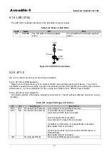
5.19. LED (D14)
The LED (D14) indicates the status of the Armadillo-9’s power supply.
Table 5-22 Status of LED (D14)
Code
Name
ON
OFF
D14
POWER
The Armadillo-9 is being supplied
power
The Armadillo-9 is not being supplied
power
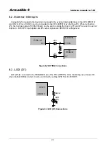
150
Ω
3.3V
Power
LED
(D14)
Figure 5-7 LED(D14) Connections
5.20. JP1-2
JP1, 2 are used to set the boot mode of the Armadillo-9.
5.20.1. JP1 (Boot ROM Selection)
Either on-board Flash memory or on-chip boot ROM can be selected as the boot device. The on-chip
boot ROM is used when executing a program downloaded via the serial (COM1) and rewriting the on-board
Flash memory. For more information on the on-chip boot ROM, refer to “EP9315 User’s Guide”.
5.20.2. JP2 (Boot Linux Selection)
JP2 allows selection of the device storing the Linux Kernel. This JP setting is effective only when Linux is
installed.
Table 5-23 Jumper Settings and Function
JP1
JP2
Boot Device
Boot Kernel
OFF
OFF
On-board Flash memory Linux Kernel of on-board Flash memory
OFF
ON
On-board Flash memory (1) If an IDE device is installed:
Linux Kernel of IDE device is booted.
(2) If Compact Flash is installed:
Linux Kernel of Compact Flash is booted.
(3) Neither an IDE device or CompactFlash is installed:
Boot loader “Hermit” is booted.
(4) A Linux Kernel is not found in either the IDE device or
CompactFlash:
Boot loader “Hermit” is booted.
ON
-
On-chip boot ROM
On-chip boot ROM program is booted.
24


