Armadillo-9
hardware manual ver.1.02
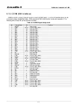
Table 5-1 Interface Details
Code
Interface
Remarks
CON1
Serial Interface 1
CON2
Serial Interface 2
Not mounted
CON3
USB Interface (Host, USB2.0, FullSpeed: 12Mbps)
Type-A connector
CON4
Parallel Interface (8bit general purpose I/O)
Not mounted
CON5
Parallel Interface (4bit general purpose I/O)
Not mounted
CON6 JTAG
Interface
Not
mounted
CON7 (Reserved)
Not
mounted
CON8 Synchronous
Serial/AC97
CODEC/I2S CODEC
Not mounted
CON9
IDE Interface (2.0mm pitch, 44-pin)
CON10
Compact Flash slot (Type I/II, I/O/Memory Card)
CON11
LAN Connector (10BASE-T/100BASE-TX) RJ-45
CON12
VGA Interface (D-Sub15 pin)
CON13
Power Supply Input Terminal (5V, 12V)
CON14
Extension Power Supply Input Terminal (-5V, -12V, RTC backup) No connector
J1, J2
PC/104 Extension Connector (stack through)
No connector
LED (D4)
IDE Access
No connector
LED (D5, 6) LAN Access ((Link, Active)
LED (D14)
Power Supply
No connector
JP1, JP2
Boot Mode Setting Jumpers
SW1 RESET
Switch
5.2. CON1 (Serial Interface 1)
CON1 is an asynchronous (start-stop) serial interface. It is connected to UART1 on the CPU (EP9315).
Signal input/output level:
RS232C
Maximum data rate:
115.2kbps
Flow Control:
CTS, RTS, DTR, DSR, DCD, RI
FIFO:
16Byte built-in for both send and receive
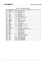
Table 5-2 CON1 Signal Assignment
No.
Signal Name
I/O
Function
1
DCD
I
Connects to EGPIO1 (Port A: 1) pin of EP9315
2
DSR
I
Connects to UART1-DSR pin of EP9315
3
RXD
I
Connects to UART1-RXD pin of EP9315
4
RTS
O
Connects to UART1-RTS pin of EP9315
5
TXD
O
Connects to UART1-TXD pin of EP9315
6
CTS
I
Connects to UART1-CTS pin of EP9315
7
DTR
O
Connects to UART1-DTR pin of EP9315
8
RI
I
Connects to EGPIO0 (Port A: 0) pin of EP9315
9
GND
Power Power supply (GND)
10
+3.3V
Power Power supply (+3.3V)
8


