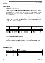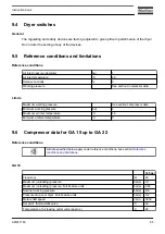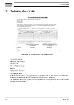
8
Problem solving
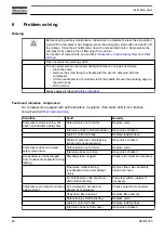
Warning
Before carrying out any maintenance, repair work or adjustment, press the stop button,
wait until the compressor has stopped, press the emergency stop button and switch off
the voltage. Close the air outlet valve, open the manual drain valve. Depressurise the
compressor by opening the oil filler plug (FC) one turn.
For location of components, see sections
,
and
.
Open and lock the isolating switch.
The air outlet valve can be locked during maintenance or repair as follows:
• Close the valve.
• Remove the screw fixing the handle with the wrench delivered with the
compressor.
• Lift the handle and turn it until the slot of the handle fits over the blocking edge on
the valve body.
• Fit the screw.
Always apply all relevant
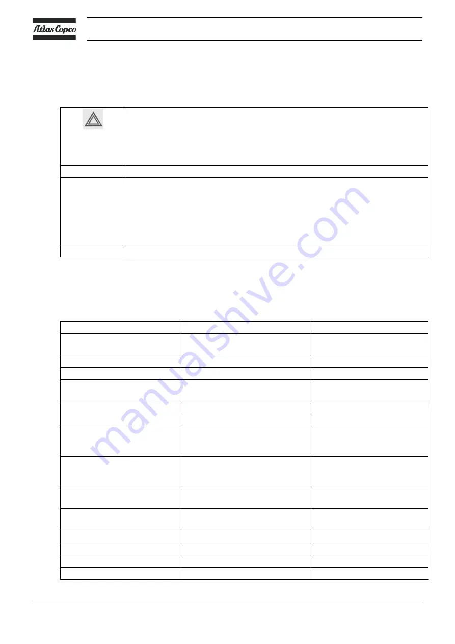
Faults and remedies, compressor
On compressors equipped with an Elektronikon I regulator, if the alarm LED is lit or flashes,
consult section
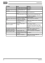
Condition
Fault
Remedy
Compressor starts running, but
does not load after a delay time
Solenoid valve out of order
Replace valve
Inlet valve stuck in closed position
Have valve checked
Leak in control air tubes
Replace leaking tubes
Minimum pressure valve leaking
(when net is depressurized)
Have valve checked
Compressor does not unload,
safety valve blows
Solenoid valve out of order
Replace valve
Inlet valve does not close
Have valve checked
Condensate is not discharged
from condensate separator during
loading
Discharge tube clogged
Check and correct as necessary
Float valve malfunctioning
(condensate drain, units without
dryer)
Remove float valve assembly,
clean and check
On Full-Feature units: electronic
drain malfunctioning
Press test button, replace if
necessary
Compressor air output or pressure
below normal
Air consumption exceeds air
delivery of compressor
Check equipment connected
Choked air filter element
Replace filter element
Solenoid valve malfunctioning
Replace valve
Leak in control air tubes
Replace leaking tubes
Inlet valve does not fully open
Have valve checked
Instruction book
80
API451763
Содержание GA18
Страница 1: ...INSTRUCTION BOOK API451763 GA 18 ...
Страница 2: ......
Страница 16: ...2 2 Air flow Flow diagrams Flow diagram GA Pack Instruction book 14 API451763 ...
Страница 56: ...4 Installation 4 1 Dimension drawings GA 15 up to GA 22 Floor mounted Pack Instruction book 54 API451763 ...
Страница 64: ...Position of oil level sight glass Electric cubicle Instruction book 62 API451763 ...
Страница 93: ......

