ATIM_ACW-DINRSM_UG_EN_V2.8
17
Transmitting information on IoT networks (Sigfox/LoRaWAN):
a.
Keep-alive frame
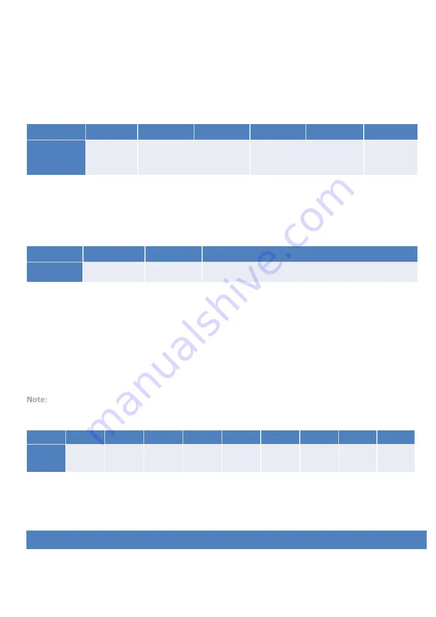
This frame is sent to the network instead of the periodic frames if no Modbus frame is
configured.
Frame format:
Byte
1
2
3
4
5
6
Data
0x01
Power supply voltage of radio core
on standby (millivolts
–
typically
3300 mV)
Power supply voltage of radio core
when transmitting (millivolts
–
typically 3300 mV)
0x64
b.
Periodic frame (or triggered by pressing button)
This frame is sent to the network at a regular, configurable interval (the statement period).
Frame format:
Byte
1
2
3,4 ...
Data
0x03
Header
Values of Modbus registers and/or bits read from the slave(s)
The header is a configurable parameter and must be set correctly in order to decode the
frame. Modbus registers are sent in a 2-byte format in MSB order.
c.
Error frame
This frame is sent to the network when a Modbus or internal error occurs. Internal errors
may arise due to an incorrect Modbus configuration.
Note:
This frame replaces a faulty radio frame. If the data in the radio frame were valid, they will be lost.
Frame format:
Byte
1
2
3
4
5
6
7
8
9
Data
0x83
Parameter
Radio
header
Error code
@Slave
Function
code
@Register
MSB
@Register
LSB
Number of
registers
The parameters of the Modbus frame are sent back to identify which frame failed. An error code is also
included to tell you which error occurred, so that you can correct your configuration if necessary. The error
codes are explained below:
Error code
Description


