ATI Technologies Flexdeburr 9150-RC-660-ER Скачать руководство пользователя страница 8

Manual, Flexdeburr, RC‑660 Series
Document #9610‑50‑1017‑10

Pinnacle Park • 1031 Goodworth Drive • Apex, NC 27539 USA • Tel: +1.919.772.0115 • Fax: +1.919.772.8259 • www.ati‑ia.com

8

2.  Product Overview

The Radially‑Compliant (RC) deburring tool, also known as Flexdeburr, is a turbine‑driven deburring unit for 

deburring aluminum, plastic, steel, etc. with a robot or CNC machine. The RC Deburring Tool is especially suited 

for removal of parting lines and flash from parts. However, its flexible design allows it to be used in a wide variety 

of applications. 

The RC deburring tool’s pneumatically controlled, articulated design allows the cutting bur to follow the part 

profile and compensate for surface irregularities while maintaining a constant, settable force. This allows high feed 

rates with uniform quality in any orientation. The tool also requires no oil, allowing clean exhaust air to be vented 

directly into the work environment.

Compliance is supported by air pressure applied to the shaft of the unit. The RC deburring tool also utilizes 

standard industrial tungsten‑carbide bits which allows for adaptation to changing assembly lines and 
part requirements. 

The RC‑660‑ER provides for (2) mounting types; a side mounting and an axial mounting. The side mounting 

provides (2) locating dowel pins and (4) threaded holes. The axial mounting utilizes a tapered flange that requires 

an adapter plate. Custom adapter plates for both side and axial mounting are available from ATI. Refer to 

Section 9—Drawings

 for more information.

The RC‑660‑ER is equipped with a 1/2" Push‑to Connect fitting to supply the motor air and a 5/32" [4 mm] Push‑to 

Connect fitting to supply the compliance air.
A tool collet system secures the bur. Many collet sizes are available to accommodate a wide variety of applications.

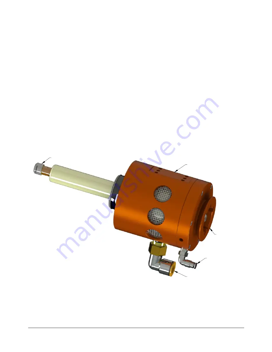
Figure 2.1—RC‑660‑ER Deburring Tool

Compliance Air

Connection

Motor Air Connection

Tool Collet

Side Mounting

Axial 

Mounting

2.1  Tool Collet Systems

All Flexdeburr products utilize removable collets to grip customer‑supplied cutting tools. Different collet 

diameters may be substituted to retain numerous cutter shank diameters. The collet retaining nut is loosened 
to open the collet allowing cutting tools to be removed and inserted. Once the tool is set to the desired depth, 
spanner wrenches are used to tighten the collet nut causing the collet to collapse and secure the cutting 
tool. The turbine motor design does not allow the installation of spindle brakes or Quick Change (drawbar) 
collet systems.

Содержание Flexdeburr 9150-RC-660-ER

Страница 1: ...e Park 1031 Goodworth Drive Apex NC 27539 USA Tel 1 919 772 0115 Fax 1 919 772 8259 www ati ia com ATI Radially Compliant Robotic Deburring Tools Flexdeburr Models 9150 RC 660 ER and 9150 RC 660 ER E...

Страница 2: ...confidential and reserved exclusively for the customers and authorized agents of ATI Industrial Automation and may not be divulged to any third party without prior written consent from ATI No warranty...

Страница 3: ...nsportation and Protection During Transportation 12 3 2 Inspection of Condition When Delivered 12 3 3 Unpacking and Handling 12 3 4 Storage and Preventive Maintenance during Storage 12 3 5 Side Mounti...

Страница 4: ...vice Procedures 25 6 1 Troubleshooting 25 6 2 Service Procedures 27 6 2 1 Bur and Collet Replacement 27 6 2 2 Turbine Motor Replacement 29 6 2 3 Ring Cylinder Assembly Replacement 33 6 2 4 Rear Housin...

Страница 5: ...g method where the direction of cutter rotation and tool motion are the same Coalescing Filter Device designed to remove liquid aerosols from the air supply lines Collet Gripping device used to hold c...

Страница 6: ...oiding the hazard and the method for avoiding the situation CAUTION Notification of information or instructions that if not followed could result in moderate injury or will cause damage to equipment T...

Страница 7: ...void the warranty Always use original ATI spare parts CAUTION Never be present near the deburring tool while it is started or in operation Flying debris and rotating parts can cause injury If it is ne...

Страница 8: ...ments The RC 660 ER provides for 2 mounting types a side mounting and an axial mounting The side mounting provides 2 locating dowel pins and 4 threaded holes The axial mounting utilizes a tapered flan...

Страница 9: ...0 0005 0 013 mm and provide a gripping range up to 0 040 1 mm This allows a standard 1 4 inch ER 11 collet to safely and accurately hold a metric 6 mm diameter cutter However the ER 11 collet system...

Страница 10: ...2 bar 90 psi The radial compliance centering air must be supplied from a regulated source between 1 0 4 1 bar 15 60 psi 2 3 1 2 Storage Table 2 2 Storage Temperature range 0 C 45 C 32 F 113 F Conditi...

Страница 11: ...ati ia com 11 Figure 2 3 RC 660 ER Series Radial Compliance Force Curves Measured at the Spindle Tip RC 660 Series Radial Contact Force 0 5 10 15 20 25 30 35 40 45 50 1 0 2 0 3 0 4 0 Centering Air Pr...

Страница 12: ...condition If there is damage to any of the packaging or if any of the goods have been exposed to abnormal handling unpack those parts that may have been damaged for a closer inspection If necessary n...

Страница 13: ...imum fastener length specified must not be exceeded or the fasteners interfere with the compliant motion of the turbine motor spindle Refer to Section 9 Drawings for more information CAUTION Lock wash...

Страница 14: ...ser of the Flexdeburr ATI can provide custom interface plates and adapters upon request An optional bench mount adapter plate allows the deburring tool to be permanently attached to a bench or other w...

Страница 15: ...ng regulator supplies air for the compliance or centering force The compliance force is applied radially and is adjusted until the desired cut is made The robot s traversing speed will also be adjuste...

Страница 16: ...nd 9150 RC 660 ER E 5 32 4 mm Quick Connect Tube Alternate Remove Supplied Fitting to use 1 8 NPT Port 1 0 4 1 bar 15 60 psi Maximum Exhaust Vented to Atmosphere through the Housing Not Applicable It...

Страница 17: ...ING Never operate the Flexdeburr product without wearing eye protection Flying debris can cause injury Always use eye protection while working in the proximity of the deburring tool CAUTION Do not use...

Страница 18: ...sh is less than the ideal speed of the deburring tool Do not use a tool that requires axial loading 4 2 4 Deburring Tool Approach Path Should be Slow and at an Angle The deburring tool should approach...

Страница 19: ...deburring frequently is loud Always use hearing protection while working in the neighborhood of the deburring cell The deburring tool should not be used to deburr materials that are prone to fracture...

Страница 20: ...to teach the path using the centerline of the bur as a guide following the edge of the part and then manually or automatically adding offsets to the robot path points to achieve the final correct bur...

Страница 21: ...opposite of bur rotation This may aid in bur stability for some operations however the cutting edge of the tool is subjected to higher friction and cutting forces Tool wear is accelerated in this mode...

Страница 22: ...deburring Without chip breaker for scratch free surfaces 9150 RC B 24063 Diamond Cut 3 8 Bur Diameter 3 4 Bur Length 1 4 Shank For hardened and tough materials super alloys and stainless steel alloyed...

Страница 23: ...4 Shank For trimming and contour milling of all glass and carbon fiber reinforced plastics Special cut geometry allows high feed rates due to low cutting forces 9150 RC B 24862 Alt Diamond Cut 1 4 Bur...

Страница 24: ...ility and therefore cannot be estimated 5 2 Lubrication Lubrication systems are not to be used The Flexdeburr air motor must be supplied with clean dry filtered air Oil in the air stream will cause th...

Страница 25: ...contact enter part at an angle Unequal compliance Worn ring cylinder Replace ring cylinder Refer to Section 6 2 3 Ring Cylinder Assembly Replacement Pivot bearing worn Replace the pivot bearing Refer...

Страница 26: ...rn Inspect spindle shaft if shaft feels loose or has play replace Refer to Section 6 2 2 Turbine Motor Replacement Chip packing of bur Too heavy a cut Decrease width of cut make multiple passes Not en...

Страница 27: ...ty 2 If the bur is to be replaced with one of an identical type measure and record the bur length extending beyond the collet lock nut Alternatively the optional ATI 9150 RC T 4230 bur setting tool ac...

Страница 28: ...1 919 772 0115 Fax 1 919 772 8259 www ati ia com 28 Figure 6 1 Bur and Collet Replacement Measure and record the length of the bur extending beyond the collet nut Spindle shaft Collet nut Bur 7 16 Ope...

Страница 29: ...to Figure 6 2 through Figure 6 6 Parts required Refer to Section 7 Serviceable Parts Tools required Small flat blade screw driver 3 mm and 5 mm hex key crescent wrench torque wrench Supplies required...

Страница 30: ...Using a 3 mm hex key remove the 6 M4 socket head cap screws holding the rear housing assembly to the front housing assembly 10 Remove the rear housing assembly also remove the O ring and alignment pi...

Страница 31: ...ey install the 6 M4 socket head cap screws that secure the rear housing to the front housing Tighten to 12 in lbs 1 4 Nm Figure 6 4 Rear Housing and Turbine Motor Installation 15 16 Apply Magnalube to...

Страница 32: ...sembly 24 Slide the boot onto the turbine motor and align the edge of the boot to the edge of the contact sleeve 25 Stretch the garter spring over the boot it seats in the groove on the contact sleeve...

Страница 33: ...7 through Figure 6 10 Parts required Refer to Section 7 Serviceable Parts Tools required Small flat head screw driver 2 mm hex key non metallic drift or arbor press Supplies required Clean rag Magnalu...

Страница 34: ...ar and front housing assemblies Figure 6 8 Ring Cylinder Removal O ring 6 6 Alignment Dowel Pin 5 Non Metallic Rod 5 Front Housing Assembly 5 6 Ring Cylinder Indicates the associated step number s in...

Страница 35: ...ws articulation of the motor assembly The pivot bearing is subject to wear and should be replaced when excessive spindle motion is observed Contact between the motor air supply fitting and the main ho...

Страница 36: ...ont Housing Assembly 7 6 6 M4 Socket Head Cap Screws 6 7 Rear Housing Assembly Washer 5 Socket Button 5 Head Cap Screws Spindle Supply Fitting 2 Compliance Air Fitting 2 9 If replacing the replacing t...

Страница 37: ...pivot bearing s ball visible from the end of the pivot bearing 18 Apply Loctite 222 to the threads of the 3 M4 socket head cap screws used to secure the large clamping washer Insert the large clamping...

Страница 38: ...ing Assembly 20 First M5 Set Screw Apply Loctite 222 19 Edge of the Outer Race Second M5 Set Screw 21 Apply Loctite 222 Rotate Pivot Ball until the Bottom surface of keyway is Flush with Edge of the O...

Страница 39: ...6 M4 socket head cap screws and use a 3 mm hex key to install the 6 M4 socket head cap screws that secure the rear housing to the front housing Tighten to 12 in lbs 1 4 Nm 29 Apply Loctite 242 to the...

Страница 40: ...ly 10 psi to the compliance air fitting Move the turbine motor spindle like a joystick and loosen or tighten the pivot bearing preload set screw until a slight resistance to motion can be felt 33 Appl...

Страница 41: ...indle motor air supply for safety 2 Disconnect the air hose from the spindle supply fitting and the compliance air fitting Refer to Figure 6 18 3 Remove the deburring tool from the robot or work locat...

Страница 42: ...ead cap screws that secure the spindle boot and boot ring to the front housing assembly Tighten to contact plus one additional flat 12 Stretch the garter spring over the boot and seat it in the groove...

Страница 43: ...by ATI 7 1 Accessories Tools and Optional Replacement Parts 1 3 2 4 6 7 8 9 5 Table 7 1 Serviceable Parts Item No Qty Part Number Description 1 1 9150 RC B XXXXX Refer to Table 4 1 for bur Part Numbe...

Страница 44: ...ed Spindle Air Pressure 6 2 Bar 90 PSI Air Consumption Idle 9 4 l s 20 CFM Air Consumption Stall 17 9 l s 38 CFM Sound Pressure Level2 78 dBa Collet Size Standard3 1 4 6 mm ER 11 Type with Large Grip...

Страница 45: ...idle 18 l s 38 CFM at stall 3 DO NOT restrict air flow or pressure to alter motor speed 4 The installed air supply fittings may be removed to utilize customer supplied 5 3 8NPT and 1 8NPT air fittings...

Страница 46: ...M6X1 0 7 MAX Note 6 Sheet 1 2X 5 5 5 MAX SF M5 Dowel Note 6 Sheet 1 52 2 42 1 Side Mounting Pattern Available if ATI Adapter Plate Kit is Not Installed 9150 RS 660 Mounting Options Rev Description In...

Страница 47: ...0 50 4207 Disk Boot Front Pivot RC RS 660 1000 13 1 3700 50 4208 Retainer Ring Disk Boot Front Pivot RS 660 RC 1000 14 1 9005 50 1035 Ring Cylinder Assembly Front Pivot RS 660 RC 1000 15 1 9005 50 104...

Страница 48: ...or in any way connected with products or services supplied hereunder may be brought more than one 1 year after the cause of action occurred No representation or agreement varying or extending the war...

Страница 49: ...for Part Numbers and pricing Premature bearing failure can occur from exposing the deburring tool to coolants and water or impacts from collisions Other failure modes that are outlined in the manual a...

Отзывы: