


22
LAN Port Configuration
VLANS
VLAN support allows segmentation of the 8 Local LAN ports into different logical LANs, each with its own address range,
and addressing method (DHCP, DHCP Relay, or static). If your U115 has been configured for VLANs, as part of
installation you will need to know which of the 8 Local LAN Ports attach to each network.
You can view the VLAN configuration through the U115 web interface as described below.
After initial power on, and once the Internet Connection has been correctly configured, the U115 will retrieve its
configuration from the network and will likely perform an automatic reboot to pick up the new configuration. This should
occur within the first 2-3 minutes after initial power on.
You will not be able to view the VLAN configuration until the
U115 has successfully retrieved its configuration.
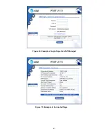
1. Following the automatic reboot open your web browser as described in
“Access the U115 Web Interface” on
page 8. It may be necessary to reboot or reconfigure your devices attached to the U115 in order to obtain/assign
a valid IP address if the IP addressing was changed when the U115 retrieved its VLAN configuration.
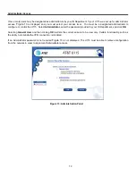
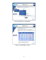
2. Click on the
Control Panel
navigation icon
.
3.
Click the entry for
Network Settings
to display the Network Settings sub-menu and click the entry for
Local LAN
Settings
4. The next window will display the Local LAN Settings. If VLANs have been configured, the display will appear as
. If VLANs have not been configured, the display will appear as in
. If no VLANs have
been configured, skip to the description for “Hub Mode” on page 25.
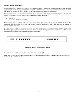
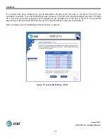
5. The display shows several rows, sorted by VLAN ID that describes which back-panel Ethernet ports are assigned
to each VLAN. The numbers in the
Port
column correspond to the numbers printed on the back of the U115.
6. Attach your Local LAN cables to an appropriate port based on designated VLAN. If more than one port has been
allocated to a VLAN, any of those ports can be used.
7. If you are not sure of the Network-to-VLAN number mapping, click on any of the VLAN ID hyperlinks to view
detailed information on the VLAN.
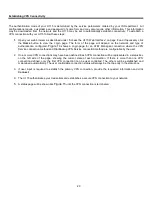
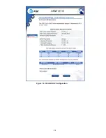
8. The next window will display the details for the VLAN. The format and content depend on factors such as
whether DHCP or DHCP relay are being used, or whether static IP addresses have been configured. In the
example for Figure 18, DHCP is configured and so the range of IP addresses and subnet mask is displayed.
Information on any addresses already given out using DHCP will also appear on this window.
9. If you are still unsure what VLAN IDs and ports apply to your local networks, contact your IS Department.
10. When complete, return to
“Establishing VPN Connectivity” on page 20.
Содержание U115
Страница 1: ...1 AT T U115 Install Guide Version D6 0 1 ...
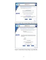
Страница 21: ...21 Figure 14 Example of Login Page for AT T Managed Figure 15 Example of Connected Page ...
Страница 23: ...23 Figure 16 Navigation to Local LAN Settings Figure 17 Local LAN Settings VLANS ...
Страница 24: ...24 Figure 18 VLAN DHCP Configuration ...