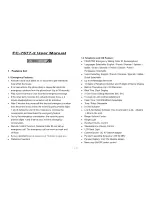
Equipment Room Hardware And Cabling Installation
49 INCHES
HORIZONTAL
LINE
AC POWER
STRIP
96 INCHES
7-11/16 INCHES
HORIZONTAL
LINE
47-1/2 INCHES
23 INCHES
7-11/16 INCHES
5-5/16 INCHES
7/8 INCH
FLOOR LINE
Figure 3-15. Mounting 900-Pair 110P-Type Terminal Blocks
(Approximately 432 4-Pair or 576 3-Pair Station
Capacity Illustrated)
of the previous screw. Partially install the second mounting screw
5-5/16 inches to the right of the screw just installed. Repeat Steps
3, 4, and 5.
If another trunk/auxiliary field terminal block is to be installed,
7 .
partially install the first screw for the terminal block, on the line, 7/8
inch to the right of the previous screw. Partially install the second
3-27
Содержание System 75
Страница 1: ...AT T AT T System 75 and System 75 XE Wiring...
Страница 2: ...AT T AT T System 75 and System 75 XE Wiring 555 200 111 Issue 2 August 1989...
Страница 16: ...System Wiring Figure 1 2 System Uniform Wiring Plan 1 7...
Страница 17: ...CHAPTER 1 INTRODUCTION Figure 1 3 Sample Uniform Wiring Installation 1 8...
Страница 29: ...CHAPTER 2 HARDWARE 66 110 Type Figure 2 1 Block Diagram of System 75 or 75 XE Installation 2 2...
Страница 35: ...CHAPTER 2 HARDWARE 66 110 Type Figure 2 4 110A Type 100 Pair Terminal Block 2 8...
Страница 36: ...110 Type Hardware Description Figure 2 5 110A Type 300 Pair Terminal Block 2 9...
Страница 98: ...Typical System Equipment Room Floor Plans 3 15...
Страница 143: ...CHAPTER 3 EQUIPMENT ROOM DESIGN 3 60...
Страница 144: ...Equipment Room Hardware And Cabling Installation 3 61...
Страница 162: ...Equipment Room Hardware And Cabling Installation 3 79...
Страница 163: ...Equipment Room Hardware And Cabling Installation 3 80...
Страница 197: ...Tables Table 4 A Recommended Protectors 4 42 v...
Страница 203: ...CHAPTER 4 STATION WIRING Figure 4 4 3 Pair to 4 Pair Wiring Labeling From Equipment Room to Information Outlet 4 6...
Страница 205: ...CHAPTER 4 STATION WIRING Figure 4 5 4 Pair Station Wiring Labeling From Equipment Room to Information Outlet 4 8...
Страница 212: ...Adjunct Powering 4 15...
Страница 214: ...Adjunct Powering 4 17...
Страница 216: ...Patch Cord Jumper Installation And Administration 4 19...
Страница 241: ...CHAPTER 4 STATION WIRING 4 44...
Страница 244: ...Miscellaneous Wiring Installation 4 47...
Страница 246: ...Miscellaneous Wiring Installation 4 49...
Страница 252: ...Miscellaneous Wiring Installation 4 55...
Страница 254: ...Miscellaneous Wiring Installation 4 57...
Страница 277: ...CHAPTER 5 AUXILIARY EQUIPMENT INSTALLATION Figure 5 1 Connections for Loudspeaker Paging and Music on Hold 5 4...
Страница 314: ...CHAPTER 5 AUXILIARY EQUIPMENT INSTALLATION 5 41...
Страница 324: ...CHAPTER 5 AUXILIARY EQUIPMENT INSTALLATION 5 51...